Image description

NOTE BOOK

MECHANICAL DIESEL

I am a text block. Click on me to drag me around or click a corner handle to resize me. Click the settings icon (it's the left one, looks like a cog) to change this text. You can type new text into me or cut and paste text from somewhere else. Click outside of me when you're done and any changes will be saved.

HEAT ENGINE


                                       Animation showing the four stages of the four-stroke combustion engine cycle:
                                                                            1. Induction (Fuel enters)
                                                                            2. Compression
                                                                            3. Ignition (Fuel is burnt)
                                                                            4. Emission (Exhaust out)


Heat engine]


Combustion engine[]

Combustion engines are heat engines driven by the heat of a combustion process.

Internal combustion engine


The internal combustion engine is an engine in which the combustion of a fuel (generally, fossil fuel) occurs with an oxidizer (usually air) in a combustion chamber. In an internal combustion engine the expansion of the high temperature and high pressure gases, which are produced by the combustion, directly applies force to components of the engine, such as the pistons or turbine blades or a nozzle, and by moving it over a distance, generates useful mechanical energy.

External combustion engine


An external combustion engine (EC engine) is a heat engine where an internal working fluid is heated by combustion of an external source, through the engine wall or a heat exchanger. The fluid then, by expanding and acting on the mechanism of the engine produces motion and usable work. The fluid is then cooled, compressed and reused (closed cycle), or (less commonly) dumped, and cool fluid pulled in (open cycle air engine).

"Combustion" refers to burning fuel with an oxidizer, to supply the heat. Engines of similar (or even identical) configuration and operation may use a supply of heat from other sources such as nuclear, solar, geothermal or exothermic reactions not involving combustion; but are not then strictly classed as external combustion engines, but as external thermal engines.

The working fluid can be a gas as in a Stirling engine, or steam as in a steam engine or an organic liquid such as n-pentane in an Organic Rankine cycle. The fluid can be of any composition; gas is by far the most common, although even single-phase liquid is sometimes used. In the case of the steam engine, the fluid changes phases between liquid and gas.

Air-breathing combustion engines

Air-breathing combustion engines are combustion engines that use the oxygen in atmospheric air to oxidise ('burn') the fuel, rather than carrying an oxidiser, as in a rocket. Theoretically, this should result in a better specific impulse than for rocket engines.

A continuous stream of air flows through the air-breathing engine. This air is compressed, mixed with fuel, ignited and expelled as the exhaust gas.

       Combustion


                                               The flames caused as a result of a fuel undergoing combustion (burning)


Combustion  or burning is a high-temperature exothermic chemical reaction between a fuel and an oxidant, usually atmospheric oxygen, that produces oxidized, often gaseous products, in a mixture termed smoke. Combustion in a fire produces a flame, and the heat produced can make combustion self-sustaining. Combustion is often a complicated sequence of elementary radical reactions. Solid fuels, such as wood, first undergo endothermic pyrolysis to produce gaseous fuels whose combustion then supplies the heat required to produce them. Combustion is often hot enough that light in the form of either glowing or a flame is produced. A simple example can be seen in the combustion of hydrogen and oxygen into water vapor, a reaction commonly used to fuel rocket engines. This reaction releases −242 kJ/mol of enthalpy (heat):

2H2(g) + O2(g) → 2H2O(g)

Uncatalyzed combustion in air requires fairly high temperatures, because quantum mechanics forbids the reaction between the rare triplet state of the familiar dioxygen and the common singlet state of fuels. Complete combustion is stoichiometric with respect to the fuel, where there is no remaining fuel, and ideally, no remaining oxidant. Thermodynamically, the chemical equilibrium of combustion in air is overwhelmingly on the side of the products. However, complete combustion is almost impossible to achieve, since the chemical equilibrium is not necessarily reached, or may contain unburnt products such as carbon monoxide, hydrogen and even carbon (soot or ash). Thus, the produced smoke is usually toxic and contains unburned or partially oxidized products. Any combustion at high temperatures in atmospheric air, which is 78 percent nitrogen, will also create small amounts of several nitrogen oxides, commonly referred to as NO
x
, since the combustion of nitrogen is thermodynamically favored at high, but not low temperatures. Since combustion is rarely clean, flue gas cleaning or catalytic converters may be required by law.

Fires occur naturally, ignited by lightning strikes or by volcanic products. Combustion (fire) was the first controlled chemical reaction discovered by humans, in the form ofcampfires and bonfires, and continues to be the main method to produce energy for humanity. Usually, the fuel is carbon, hydrocarbons or more complicated mixtures such aswood that contains partially oxidized hydrocarbons. The thermal energy produced from combustion of either fossil fuels such as coal or oil, or from renewable fuels such asfirewood, is harvested for diverse uses such as cooking, production of electricity or industrial or domestic heating. Combustion is also currently the only reaction used to powerrockets. Combustion is also used to destroy (incinerate) waste, both nonhazardous and hazardous.

Oxidants for combustion have high oxidation potential and include atmospheric or pure oxygen, chlorine, fluorine, chlorine trifluoride, nitrous oxide and nitric acid. For instance,hydrogen burns in chlorine to form hydrogen chloride with the liberation of heat and light characteristic of combustion. Although usually not catalyzed, combustion can be catalyzed by platinum or vanadium, as in the contact process.

      Internal combustion engine


                                              Diagram of a cylinder as found in 4 stroke gasoline engines. Caption:
                                                                             C – crankshaft.
                                                                             E – exhaust camshaft.
                                                                             I – inlet camshaft.
                                                                             P – piston.
                                                                             R – connecting rod.
                                                                             S – spark plug.
                                                                             V – valves. red: exhaust, blue: intake.
                                                                             W – cooling water jacket.
                                                                          gray structure – engine block.


An internal combustion engine (ICE) is an engine where the combustion of a fuel occurs with an oxidizer (usually air) in a combustion chamber that is an integral part of the working fluid flow circuit. In an internal combustion engine the expansion of the high-temperature and high-pressure gases produced by combustion apply direct force to some component of the engine. The force is applied typically to pistons,turbine blades, or a nozzle. This force moves the component over a distance, transforming chemical energy into useful mechanical energy. The first commercially successful internal combustion engine was created by Étienne Lenoir around 1859.

Typically an ICE is fed with fossil fuels like natural gas or petroleum products such as gasoline, diesel fuel or fuel oil. There's a growing usage of renewable fuels like biodiesel for compression ignition engines and bioethanol for spark ignition engines. Hydrogen can be used as a fuel, where it would act as an energy carrier rather than as a primary energy source because it is not found unbounded in nature in appreciable quantities. It is possible to generate pure hydrogen from renewable energy. See hydrogen economy.

The term internal combustion engine usually refers to an engine in which combustion is intermittent, such as the more familiar four-strokeand two-stroke piston engines, along with variants, such as the six-stroke piston engine and the Wankel rotary engine. A second class of internal combustion engines use continuous combustion: gas turbines, jet engines and most rocket engines, each of which are internal combustion engines on the same principle as previously described. Firearms are also a form of internal combustion engine.

Internal combustion engines are quite different from external combustion engines, such as steam or Stirling engines, in which the energy is delivered to a working fluid not consisting of, mixed with, or contaminated by combustion products. Working fluids can be air, hot water,pressurized water or even liquid sodium, heated in a boiler. ICEs are usually powered by energy-dense fuels such as gasoline or diesel, liquids derived from fossil fuels. While there are many stationary applications, most ICEs are used in mobile applications and are the dominant power supply for cars, aircraft, and boats.

        External combustion engine


               Model Stirling engine, with external heat from a spirit lamp (bottom right) applied to the outside of the glass displacer cylinder.
                                                                       
 
                            Newcomen's engine, a precursor of the steam engine, with the boiler heated from beneath
                                                                 
 
               Sectioned steam locomotive. Although the fire is within an enclosedfirebox, this is still an externalcombustion engine,
                as the exhaust gas and the steam working fluid are kept separate.

An external combustion engine (EC engine) is a heat engine where an (internal) working fluid is heated by combustion in an external source, through the engine wall or a heat exchanger. The fluid then, by expanding and acting on the mechanism of the engine, produces motion and usable work. The fluid is then cooled, compressed and reused (closed cycle), or (less commonly) dumped, and cool fluid pulled in (open cycle air engine).


Con

Combustion

"Combustion" refers to burning fuel with an oxidizer, to supply the heat. Engines of similar (or even identical) configuration and operation may use a supply of heat from other sources such as nuclear, solar, geothermal or exothermic reactions not involving combustion; but are not then strictly classed as external combustion engines, but as external thermal engines.

                Stirling engin .


Alpha type Stirling engine. There are two cylinders. The expansion cylinder (red) is maintained at a high temperature while the compression cylinder (blue) is cooled. The passage between the two cylinders contains the regenerator.
                                                                                           
 
Beta type Stirling engine. There is only one cylinder, hot at one end and cold at the other. A loose fitting displacer shunts the air between the hot and cold ends of the cylinder. A power piston at the end of the cylinder drives the flywheel.


Stirling engine is a heat engine that operates by cyclic compression and expansion of air or other gas (the working fluid) at different temperatures, such that there is a net conversion of heat energy to mechanical work. More specifically, a closed-cycle regenerative heat engine with a permanently gaseous working fluid. Closed-cycle, in this context, means a thermodynamic system in which the working fluid is permanently contained within the system, and regenerative describes the use of a specific type of internal heat exchanger and thermal store, known as the regenerator. The inclusion of a regenerator differentiates the Stirling engine from other closed cycle hot air engines.

Originally conceived in 1816 as an industrial prime mover to rival the steam engine, its practical use was largely confined to low-power domestic applications for over a century.

The Stirling engine is noted for high efficiency compared to steam engines, quiet operation, and its ability to use almost any heat source. This compatibility with alternative and renewable energy sources has become increasingly significant as the price of conventional fuels rises, and also in light of concerns such as peak oil and climate change. This engine is currently exciting interest as the core component ofmicro combined heat and power (CHP) units, in which it is more efficient and safer than a comparable steam engine.

Contents

Name and classification

Robert Stirling was a Scottish minister who invented the first practical example of a closed cycle air engine in 1816, and it was suggested by Fleeming Jenkin as early as 1884 that all such engines should therefore generically be called Stirling engines. This naming proposal found little favour, and the various types on the market continued to be known by the name of their individual designers or manufacturers, e.g., Rider's, Robinson's, or Heinrici's (hot) air engine. In the 1940s, the Philips company was seeking a suitable name for its own version of the 'air engine', which by that time had been tested with working fluids other than air, and decided upon 'Stirling engine' in April 1945.[7] However, nearly thirty years later, Graham Walker still had cause to bemoan the fact such terms as 'hot air engine' remained interchangeable with 'Stirling engine', which itself was applied widely and indiscriminately;[8] a situation that continues.[9]

Like the steam engine, the Stirling engine is traditionally classified as an external combustion engine, as all heat transfers to and from the working fluid take place through a solid boundary (heat exchanger) thus isolating the combustion process and any contaminants it may produce from the working parts of the engine. This contrasts with an internal combustion engine where heat input is by combustion of a fuel within the body of the working fluid. Most of the many possible implementations of the Stirling engine fall into the category of reciprocating piston engine.

History[edit]

Invention and early development[edit]


         Illustration from Robert Stirling's 1816 patent application of the air engine design which later came to be known as the Stirling Engine


The Stirling engine (or Stirling's air engine as it was known at the time) was invented and patented by Robert Stirling in 1816. It followedearlier attempts at making an air engine but was probably the first put to practical use when, in 1818, an engine built by Stirling was employed pumping water in a quarry. The main subject of Stirling's original patent was a heat exchanger, which he called an "economiser" for its enhancement of fuel economy in a variety of applications. The patent also described in detail the employment of one form of the economiser in his unique closed-cycle air engine design in which application it is now generally known as a "regenerator". Subsequent development by Robert Stirling and his brother James, an engineer, resulted in patents for various improved configurations of the original engine including pressurization, which by 1843, had sufficiently increased power output to drive all the machinery at a Dundeeiron foundry.

Though it has been disputed, it is widely supposed that as well as saving fuel, the inventors were motivated to create a safer alternative to the steam engines of the time, whose boilers frequently exploded, causing many injuries and fatalities.

The need for Stirling engines to run at very high temperatures to maximize power and efficiency exposed limitations in the materials of the day, and the few engines that were built in those early years suffered unacceptably frequent failures (albeit with far less disastrous consequences than a boiler explosion[18]) — for example, the Dundee foundry engine was replaced by a steam engine after three hot cylinder failures in four years.

Later nineteenth century[edit]


                               A typical late nineteenth/early twentieth century water pumping engine by the Rider-Ericsson Engine Company

Subsequent to the failure of the Dundee foundry engine there is no record of the Stirling brothers having any further involvement with air engine development and the Stirling engine never again competed with steam as an industrial scale power source (steam boilers were becoming safer and steam engines more efficient, thus presenting less of a target to rival prime movers). However, from about 1860 smaller engines of the Stirling/hot air type were produced in substantial numbers finding applications wherever a reliable source of low to medium power was required, such as raising water or providing air for church organs. These generally operated at lower temperatures so as not to tax available materials, so were relatively inefficient. Their selling point was that, unlike a steam engine, they could be operated safely by anybody capable of managing a fire. Several types remained in production beyond the end of the century, but apart from a few minor mechanical improvements the design of the Stirling engine in general stagnated during this period.

Twentieth century revival

During the early part of the twentieth century the role of the Stirling engine as a "domestic motor" was gradually taken over by theelectric motor and small internal combustion engines. By the late 1930s, it was largely forgotten, only produced for toys and a few small ventilating fans.

Around that time, Philips was seeking to expand sales of its radios into parts of the world where electricity and batteries were not consistently available. Philips' management decided that offering a low-power portable generator would facilitate such sales and asked a group of engineers at the company's research lab in Eindhoven to evaluate alternative ways of achieving this aim. After a systematic comparison of various prime movers, the team decided to go forward with the Stirling engine, citing its quiet operation (both audibly and in terms of radio interference) and ability to run on a variety of heat sources (common lamp oil – "cheap and available everywhere" – was favored). They were also aware that, unlike steam and internal combustion engines, virtually no serious development work had been carried out on the Stirling engine for many years and asserted that modern materials and know-how should enable great improvements.

By 1951, the 180/200 W generator set designated MP1002CA (known as the "Bungalow set") was ready for production and an initial batch of 250 was planned, but soon it became clear that they could not be made at a competitive price. Additionally, the advent of transistor radios and their much lower power requirements meant that the original rationale for the set was disappearing. Approximately 150 of these sets were eventually produced. Some found their way into university and college engineering departments around the world giving generations of students a valuable introduction to the Stirling engine.


Philips MP1002CA Stirling generator of 1951

In parallel with the Bungalow set, Philips developed experimental Stirling engines for a wide variety of applications and continued to work in the field until the late 1970s, but only achieved commercial success with the 'reversed Stirling engine' cryocooler. However, they filed a large number of patents and amassed a wealth of information, which they licensed to other companies and which formed the basis of much of the development work in the modern era.

Functional description[edit]

The engine is designed so that the working gas is generally compressed in the colder portion of the engine and expanded in the hotter portion resulting in a net conversion of heat into work. An internal regenerative heat exchanger increases the Stirling engine's thermal efficiency compared to simpler hot air engines lacking this feature.

Key components[edit]

                                                                           BetaStirlingTG4web.svg

                                                                             Cut-away diagram of a rhombic drive beta configuration Stirling engine design:

  1. Pink – Hot cylinder wall
  2. Dark grey – Cold cylinder wall
  3. Yellow – Coolant inlet and outlet pipes
  4. Dark green – Thermal insulation separating the two cylinder ends
  5. Light green – Displacer piston
  6. Dark blue – Power piston
  7. Light blue – Linkage crank and flywheels
Not shown: Heat source and heat sinks. In this design the displacer piston is constructed without a purpose-built regenerator.


As a consequence of closed cycle operation, the heat driving a Stirling engine must be transmitted from a heat source to the working fluid by heat exchangers and finally to a heat sink. A Stirling engine system has at least one heat source, one heat sink and up to five[clarification needed] heat exchangers. Some types may combine or dispense with some of these.

Heat source


                    Point focus parabolic mirror with Stirling engine at its center and its solar tracker at Plataforma Solar de Almería(PSA) in Spain
                                                                     
 
                                                                                Dish Stirling from SES


The heat source may be provided by the combustion of a fuel and, since the combustion products do not mix with the working fluid and hence do not come into contact with the internal parts of the engine, a Stirling engine can run on fuels that would damage other engines type's internals, such as landfill gas, which contains siloxane.

Other suitable heat sources include concentrated solar energy, geothermal energy, nuclear energy, waste heat and bioenergy. If solar power is used as a heat source, regular solar mirrors and solar dishes may be utilised. The use of Fresnel lenses and mirrors has also been advocated, for example in planetary surface exploration.[31] Solar powered Stirling engines are increasingly popular as they offer an environmentally sound option for producing power while some designs are economically attractive in development projects.

Heater / hot side heat exchanger

In small, low power engines this may simply consist of the walls of the hot space(s) but where larger powers are required a greater surface area is needed to transfer sufficient heat. Typical implementations are internal and external fins or multiple small bore tubes.

Designing Stirling engine heat exchangers is a balance between high heat transfer with lowviscous pumping losses and low dead space (unswept internal volume). Engines that operate at high powers and pressures require that heat exchangers on the hot side be made of alloys that retain considerable strength at temperature and that don't corrode or creep.

Regenerator


In a Stirling engine, the regenerator is an internal heat exchanger and temporary heat store placed between the hot and cold spaces such that the working fluid passes through it first in one direction then the other, taking heat from the fluid in one direction, and returning it in the other. It can be as simple as metal mesh or foam, and benefits from high surface area, high heat capacity, low conductivity and low flow friction. Its function is to retain within the system that heat that would otherwise be exchanged with the environment at temperatures intermediate to the maximum and minimum cycle temperatures, thus enabling the thermal efficiency of the cycle to approach the limiting Carnotefficiency.

The primary effect of regeneration in a Stirling engine is to increase the thermal efficiency by 'recycling' internal heat that would otherwise pass through the engine irreversibly. As a secondary effect, increased thermal efficiency yields a higher power output from a given set of hot and cold end heat exchangers. These usually limit the engine's heat throughput. In practice this additional power may not be fully realized as the additional "dead space" (unswept volume) and pumping loss inherent in practical regenerators reduces the potential efficiency gains from regeneration.

The design challenge for a Stirling engine regenerator is to provide sufficient heat transfer capacity without introducing too much additional internal volume ('dead space') or flow resistance. These inherent design conflicts are one of many factors that limit the efficiency of practical Stirling engines. A typical design is a stack of fine metal wire meshes, with low porosity to reduce dead space, and with the wire axes perpendicular to the gas flow to reduce conduction in that direction and to maximize convective heat transfer.

The regenerator is the key component invented by Robert Stirling and its presence distinguishes a true Stirling engine from any other closed cycle hot air engine. Many small 'toy' Stirling engines, particularly low-temperature difference (LTD) types, do not have a distinct regenerator component and might be considered hot air engines, however a small amount of regeneration is provided by the surface of the displacer itself and the nearby cylinder wall, or similarly the passage connecting the hot and cold cylinders of an alpha configuration engine.

Cooler / cold side heat exchanger

In small, low power engines this may simply consist of the walls of the cold space(s), but where larger powers are required a cooler using a liquid like water is needed to transfer sufficient heat.

Heat sink

The heat sink is typically the environment at ambient temperature. In the case of medium to high power engines, a radiator is required to transfer the heat from the engine to the ambient air. Marine engines can use the ambient water. In the case of combined heat and power systems, the engine's cooling water is used directly or indirectly for heating purposes.

Alternatively, heat may be supplied at ambient temperature and the heat sink maintained at a lower temperature by such means as cryogenic fluid (see Liquid nitrogen economy) or iced water.

Displacer

The displacer is a special-purpose piston, used in Beta and Gamma type Stirling engines, to move the working gas back and forth between the hot and cold heat exchangers. Depending on the type of engine design, the displacer may or may not be sealed to the cylinder, i.e. it may be a loose fit within the cylinder, allowing the working gas to pass around it as it moves to occupy the part of the cylinder beyond.

Configurations[edit]

There are three major types of Stirling engines, that are distinguished by the way they move the air between the hot and cold areas:

  1. The alpha configuration has two power pistons, one in a hot cylinder, one in a cold cylinder, and the gas is driven between the two by the pistons; it is typically in a V-formation with the pistons joined at the same point on a crankshaft.
  2. The beta configuration has a single cylinder with a hot end and a cold end, containing a power piston and a 'displacer' that drives the gas between the hot and cold ends. It is typically used with a rhombic drive to achieve the phase difference between the displacer and power pistons, but they can be joined 90 degress out of phase on a crankshaft.
  3. The gamma configuration has two cylinders: one containing a displacer, with a hot and a cold end, and one for the power piston; they are joined to form a single space with the same pressure in both cylinders; the pistons are typically in parallel and joined 90 degrees out of phase on a crankshaft.

Alpha Configuration Operation

An Alpha Stirling contains two power pistons in separate cylinders, one hot and one cold. The hot cylinder is situated inside the high temperature heat exchanger and the cold cylinder is situated inside the low temperature heat exchanger. This type of engine has a high power-to-volume ratio but has technical problems due to the usually high temperature of the hot piston and the durability of its seals.[In practice, this piston usually carries a large insulating head to move the seals away from the hot zone at the expense of some additional dead space.

The following diagrams do not show internal heat exchangers in the compression and expansion spaces, which are needed to produce power. A regenerator would be placed in the pipe connecting the two cylinders.

Alpha Stirling frame 12.svg
1. Most of the working gas is in contact with the hot cylinder walls, it has been heated and expansion has pushed the hot piston to the bottom of its travel in the cylinder. The expansion continues in the cold cylinder, which is 90° behind the hot piston in its cycle, extracting more work from the hot gas.
Alpha Stirling frame 16.svg
2. The gas is now at its maximum volume. The hot cylinder piston begins to move most of the gas into the cold cylinder, where it cools and the pressure drops.
Alpha Stirling frame 4.svg
3. Almost all the gas is now in the cold cylinder and cooling continues. The cold piston, powered by flywheel momentum (or other piston pairs on the same shaft) compresses the remaining part of the gas.
Alpha Stirling frame 8.svg
4. The gas reaches its minimum volume, and it now expands in the hot cylinder where it is heated once more, driving the hot piston in its power stroke.
Alpha Stirling.gif
The complete alpha type Stirling cycle. Note that if the application of heat and cold is reversed, the engine runs in the opposite direction without any other changes.

Beta Configuration Operation[edit]

beta Stirling has a single power piston arranged within the same cylinder on the same shaft as a displacer piston. The displacer piston is a loose fit and does not extract any power from the expanding gas but only serves to shuttle the working gas between the hot and cold heat exchangers. When the working gas is pushed to the hot end of the cylinder it expands and pushes the power piston. When it is pushed to the cold end of the cylinder it contracts and the momentum of the machine, usually enhanced by a flywheel, pushes the power piston the other way to compress the gas. Unlike the alpha type, the beta type avoids the technical problems of hot moving seals.[37]

Again, the following diagrams do not show any internal heat exchangers or a regenerator, which would be placed in the gas path around the displacer. If a regenerator is used in a beta engine, it is usually in the position of the displacer and moving, often as a volume of wire mesh.

Beta Stirling frame 12.png
1. Power piston (dark grey) has compressed the gas, the displacer piston (light grey) has moved so that most of the gas is adjacent to the hot heat exchanger.
Beta Stirling frame 16.png
2. The heated gas increases in pressure and pushes the power piston to the farthest limit of the power stroke.
Beta Stirling frame 4.png
3. The displacer piston now moves, shunting the gas to the cold end of the cylinder.
Beta Stirling frame 8.png
4. The cooled gas is now compressed by the flywheel momentum. This takes less energy, since its pressure drops when it is cooled.
Stirling Animation.gif
The complete beta type Stirling cycle

Gamma Configuration Operation

gamma Stirling is simply a beta Stirling in which the power piston is mounted in a separate cylinder alongside the displacer piston cylinder, but is still connected to the same flywheel. The gas in the two cylinders can flow freely between them and remains a single body. This configuration produces a lower compression ratio because of the volume of the connection between the two but is mechanically simpler and often used in multi-cylinder Stirling engines.

Other types

Other Stirling configurations continue to interest engineers and inventors.

The rotary Stirling engine seeks to convert power from the Stirling cycle directly into torque, similar to the rotary combustion engine. No practical engine has yet been built but a number of concepts, models and patents have been produced for example the Quasiturbine engine.[38]

The hybrid between piston and rotary configuration is a double acting engine. This design rotates the displacers on either side of the power piston


Top view of two rotating displacer powering the horizontal piston. Regenerators and radiator removed for clarity

Another alternative is the Fluidyne engine (Fluidyne heat pump), which uses hydraulic pistons to implement the Stirling cycle. The work produced by a Fluidyne engine goes into pumping the liquid. In its simplest form, the engine contains a working gas, a liquid and two non-return valves.

The Ringbom engine concept published in 1907 has no rotary mechanism or linkage for the displacer. This is instead driven by a small auxiliary piston, usually a thick displacer rod, with the movement limited by stops.

The two-cylinder Stirling with Ross yoke is a two-cylinder stirling engine (not positioned at 90°, but at 0°) connected with a special yoke. The engine configuration/yoke setup was invented by Andy Ross (engineer).

The Franchot engine is a double acting engine invented by ‘Franchot’ in the nineteenth century. A double acting engine is one where both sides of the piston are acted upon by the pressure of the working fluid. One of the simplest forms of a double acting machine, the Franchot engine consists of two pistons and two cylinders and acts like two separate alpha machines. In the Franchot engine, each piston acts in two gas phases, which makes more efficient use of the mechanical components than a single acting alpha machine. However, a disadvantage of this machine is that one connecting rod must have a sliding seal at the hot side of the engine, which is a difficult task when dealing with high pressures and high temperatures

Free piston Stirling engines


Various free-piston Stirling configurations... F."free cylinder", G. Fluidyne, H. "double-acting" Stirling (typically 4 cylinders)

"Free piston" Stirling engines include those with liquid pistons and those with diaphragms as pistons. In a "free piston" device, energy may be added or removed by an electrical linear alternator, pump or other coaxial device. This avoids the need for a linkage, and reduces the number of moving parts. In some designs, friction and wear are nearly eliminated by the use of non-contact gas bearings or very precise suspension through planar springs.

Four basic steps in the cycle of a “Free piston” Stirling engine,

  1. The power piston is pushed outwards by the expanding gas thus doing work. Gravity plays no role in the cycle.
  2. The gas volume in the engine increases and therefore the pressure reduces, which causes a pressure difference across the displacer rod to force the displacer towards the hot end. When the displacer moves the piston is almost stationary and therefore the gas volume is almost constant. This step results in the constant volume cooling process, which reduces the pressure of the gas.
  3. The reduced pressure now arrests the outward motion of the piston and it begins to accelerate towards the hot end again and by its own inertia, compresses the now cold gas, which is mainly in the cold space.
  4. As the pressure increases, a point is reached where the pressure differential across the displacer rod becomes large enough to begin to push the displacer rod (and therefore also the displacer) towards the piston and thereby collapsing the cold space and transferring the cold, compressed gas towards the hot side in an almost constant volume process. As the gas arrives in the hot side the pressure increases and begins to move the piston outwards to initiate the expansion step as explained in .

In the early 1960s, W.T. Beale invented a free piston version of the Stirling engine to overcome the difficulty of lubricating the crank mechanism.[42] While the invention of the basic free piston Stirling engine is generally attributed to Beale, independent inventions of similar types of engines were made by E.H. Cooke-Yarborough and C. West at the Harwell Laboratories of the UKAERE.[43] G.M. Benson also made important early contributions and patented many novel free-piston configurations.[44]

The first known mention of a Stirling cycle machine using freely moving components is a British patent disclosure in 1876.[45] This machine was envisaged as a refrigerator (i.e., thereversed Stirling cycle). The first consumer product to utilize a free piston Stirling device was a portable refrigerator manufactured by Twinbird Corporation of Japan and offered in the US by Coleman in 2004.

Flat Stirling engine
                                                                              
 
Cutaway of the flat Stirling engine: 10.Hot cylinder 11.A volume of hot cylinder 12.B volume of hot cylinder 17.Warm piston diaphragm 18.Heating medium 19.Piston rod 20.Cold cylinder 21.A Volume of cold cylinder 22.B Volume of cold cylinder 27.Cold piston diaphragm 28.Coolant medium 30.Working cylinder 31.A volume of working cylinder 32.B volume of working cylinder 37.Working piston diaphragm 41.Regenerator mass of A volume 42.Regenerator mass of B volume 48.Heat accumulator 50.Thermal insulation 60.Generator 63.Magnetic circuit 64.Electrical winding 70.Channel connecting warm and working cylinders


Design of the flat double-acting Stirling engine solves the drive of a displacer with the help of the fact that areas of the hot and cold pistons of the displacer are different. The drive does so without any mechanical transmission . Using diaphragms eliminates friction and need for lubricants. When the displacer is in motion, the generator holds the working piston in the limit position, which brings the engine working cycle close to an ideal Stirling cycle. The ratio of the area of the heat exchangers to the volume of the machine increases by the implementation of a flat design. Flat design of the working cylinder approximates thermal process of the expansion and compression closer to the isothermal one. The disadvantage is a large area of the thermal insulation between the hot and cold space. [46]

Thermoacoustic cycle

Thermoacoustic devices are very different from Stirling devices, although the individual path travelled by each working gas molecule does follow a real Stirling cycle. These devices include the thermoacoustic engine and thermoacoustic refrigerator. High-amplitude acousticstanding waves cause compression and expansion analogous to a Stirling power piston, while out-of-phase acoustic travelling waves cause displacement along a temperature gradient, analogous to a Stirling displacer piston. Thus a thermoacoustic device typically does not have a displacer, as found in a beta or gamma Stirling.

Other developments[edit]

Starting in 1986, Infinia Corporation began developing both highly reliable pulsed free-piston Stirling engines, and thermoacoustic coolers using related technology. The published design uses flexural bearings and hermetically sealed Helium gas cycles, to achieve tested reliabilities exceeding 20 years. As of 2010, the corporation had amassed more than 30 patents, and developed a number of commercial products for both combined heat and power, and solar power.[47] More recently, NASA has considered nuclear-decay heated Stirling Engines for extended missions to the outer solar system.[48] At the recent Cable-Tec Expo put on by the Society of Cable Telecommunications Engineers, Dean Kamen took the stage with Time Warner Cable Chief Technology Officer Mike LaJoie to announce a new initiative between his company Deka Research and the SCTE. Kamen refers to it as a Stirling engine.[49][50]

Theory[edit]

Main article: Stirling cycle
                                                                       
 
A pressure/volume graph of the idealized Stirling cycle

The idealised Stirling cycle consists of four thermodynamic processes acting on the working fluid:

  1. Isothermal Expansion. The expansion-space and associated heat exchanger are maintained at a constant high temperature, and the gas undergoes near-isothermal expansion absorbing heat from the hot source.
  2. Constant-Volume (known as isovolumetric or isochoric) heat-removal. The gas is passed through the regenerator, where it cools, transferring heat to the regenerator for use in the next cycle.
  3. Isothermal Compression. The compression space and associated heat exchanger are maintained at a constant low temperature so the gas undergoes near-isothermal compression rejecting heat to the cold sink
  4. Constant-Volume (known as isovolumetric or isochoric) heat-addition. The gas passes back through the regenerator where it recovers much of the heat transferred in 2, heating up on its way to the expansion space.

Theoretical thermal efficiency equals that of the hypothetical Carnot cycle - i.e. the highest efficiency attainable by any heat engine. However, though it is useful for illustrating general principles, the ideal cycle deviates substantially from practical Stirling engines. It has been argued that its indiscriminate use in many standard books on engineering thermodynamics has done a disservice to the study of Stirling engines in general.

Other real-world issues reduce the efficiency of actual engines, due to limits of convective heat transfer, and viscous flow (friction). There are also practical mechanical considerations, for instance a simple kinematic linkage may be favoured over a more complex mechanism needed to replicate the idealized cycle, and limitations imposed by available materials such as non-ideal properties of the working gas, thermal conductivity, tensile strength, creep, rupture strength, and melting point. A question that often arises is whether the ideal cycle with isothermal expansion and compression is in fact the correct ideal cycle to apply to the Stirling engine. Professor C. J. Rallis has pointed out that it is very difficult to imagine any condition where the expansion and compression spaces may approach isothermal behavior and it is far more realistic to imagine these spaces asadiabatic. An ideal analysis where the expansion and compression spaces are taken to be adiabatic with isothermal heat exchangers and perfect regeneration was analyzed by Rallis and presented as a better ideal yardstick for Stirling machinery. He called this cycle the 'pseudo-Stirling cycle' or 'ideal adiabatic Stirling cycle'. An important consequence of this ideal cycle is that it does not predict Carnot efficiency. A further conclusion of this ideal cycle is that maximum efficiencies are found at lower compression ratios, a characteristic observed in real machines. In an independent work, T. Finkelstein also assumed adiabatic expansion and compression spaces in his analysis of Stirling machinery

Operation[edit]

Since the Stirling engine is a closed cycle, it contains a fixed mass of gas called the "working fluid", most commonly air, hydrogen or helium. In normal operation, the engine is sealed and no gas enters or leaves the engine. No valves are required, unlike other types of piston engines. The Stirling engine, like most heat engines, cycles through four main processes: cooling, compression, heating and expansion. This is accomplished by moving the gas back and forth between hot and cold heat exchangers, often with a regeneratorbetween the heater and cooler. The hot heat exchanger is in thermal contact with an external heat source, such as a fuel burner, and the cold heat exchanger being in thermal contact with an external heat sink, such as air fins. A change in gas temperature causes a corresponding change in gas pressure, while the motion of the piston causes the gas to be alternately expanded and compressed.

The gas follows the behaviour described by the gas laws that describe how a gas' pressure, temperature and volume are related. When the gas is heated, because it is in a sealed chamber, the pressure rises and this then acts on the power piston to produce a power stroke. When the gas is cooled the pressure drops and this means that less work needs to be done by the piston to compress the gas on the return stroke, thus yielding a net power output.

The ideal Stirling cycle is unattainable in the real world, and the actual Stirling cycle is inherently less efficient than the Otto cycle of internal combustion engines. The efficiency of Stirling machines is linked to the environmental temperature; a higher efficiency is obtained when the weather is cooler, thus making this type of engine less interesting in places with warmer climates. As with other external combustion engines, Stirling engines can use heat sources other than from combustion of fuels.

When one side of the piston is open to the atmosphere, the operation is slightly different. As the sealed volume of working gas comes in contact with the hot side, it expands, doing work on both the piston and on the atmosphere. When the working gas contacts the cold side, its pressure drops below atmospheric pressure and the atmosphere pushes on the piston and does work on the gas.

To summarize, the Stirling engine uses the temperature difference between its hot end and cold end to establish a cycle of a fixed mass of gas, heated and expanded, and cooled and compressed, thus converting thermal energy into mechanical energy. The greater the temperature difference between the hot and cold sources, the greater the thermal efficiency. The maximum theoretical efficiency is equivalent to the Carnot cycle, however the efficiency of real engines is less than this value due to friction and other losses.

                                                                             File:Sterling engine small clear.ogg
 
                                             Video showing the compressor and displacer of a very small Stirling Engine in action


Very low-power engines have been built that run on a temperature difference of as little as 0.5 K. In a displacer type stirling engineyou have one piston and one displacer. A temperature difference is required between the top and bottom of the large cylinder to run the engine. In the case of the low-temperature difference (LTD) stirling engine, temperature difference between your hand and the surrounding air can be enough to run the engine. The power piston in the displacer type stirling engine, is tightly sealed and is controlled to move up and down as the gas inside expands. The displacer on the other hand is very loosely fitted so that air can move freely between the hot and cold sections of the engine as the piston moves up and down. The displacer moves up and down to control the heating and cooling of the gas in the engine.

There are two positions,

  1. When the displacer is near the top of the large cylinder; inside the engine most of the gas has been heated by the heat source and it expands. This increases the pressure, which forces the piston up.
  2. When the displacer is near the bottom of the large cylinder; most of the gas in the engine has now cooled and contracts causing the pressure to decrease, which in turn allows the piston to move down and compress the gas.

Pressurization[edit]

In most high power Stirling engines, both the minimum pressure and mean pressure of the working fluid are above atmospheric pressure. This initial engine pressurization can be realized by a pump, or by filling the engine from a compressed gas tank, or even just by sealing the engine when the mean temperature is lower than the mean operating temperature. All of these methods increase the mass of working fluid in the thermodynamic cycle. All of the heat exchangers must be sized appropriately to supply the necessary heat transfer rates. If the heat exchangers are well designed and can supply the heat flux needed for convective heat transfer, then the engine, in a first approximation, produces power in proportion to the mean pressure, as predicted by the West number, and Beale number. In practice, the maximum pressure is also limited to the safe pressure of thepressure vessel. Like most aspects of Stirling engine design, optimization is multivariate, and often has conflicting requirements. A difficulty of pressurization is that while it improves the power, the heat required increases proportionately to the increased power. This heat transfer is made increasingly difficult with pressurization since increased pressure also demands increased thicknesses of the walls of the engine, which, in turn, increase the resistance to heat transfer.

Lubricants and friction[edit]


                              A modern Stirling engine and generator set with 55 kW electrical output, for combined heat and power applications


 At high temperatures and pressures, the oxygen in air-pressurized crankcases, or in the working gas of hot air engines, can combine with the engine's lubricating oil and explode. At least one person has died in such an explosion.

Lubricants can also clog heat exchangers, especially the regenerator. For these reasons, designers prefer non-lubricated, low-coefficient of friction materials (such as rulon or graphite), with low normal forces on the moving parts, especially for sliding seals. Some designs avoid sliding surfaces altogether by using diaphragms for sealed pistons. These are some of the factors that allow Stirling engines to have lower maintenance requirements and longer life than internal-combustion engines.

Analysis

Comparison with internal combustion engines[edit]

In contrast to internal combustion engines, Stirling engines have the potential to use renewable heat sources more easily, to be quieter, and to be more reliable with lower maintenance. They are preferred for applications that value these unique advantages, particularly if the cost per unit energy generated is more important than the capital cost per unit power. On this basis, Stirling engines are cost competitive up to about 100 kW.

Compared to an internal combustion engine of the same power rating, Stirling engines currently have a higher capital cost and are usually larger and heavier. However, they are more efficient than most internal combustion engines. Their lower maintenance requirements make the overall energy cost comparable. The thermal efficiency is also comparable (for small engines), ranging from 15% to 30%. For applications such as micro-CHP, a Stirling engine is often preferable to an internal combustion engine. Other applications include water pumping, astronautics, and electrical generation from plentiful energy sources that are incompatible with the internal combustion engine, such as solar energy, and biomass such as agricultural waste and other waste such as domestic refuse. Stirlings are also used as a marine engine in Swedish Gotland-class submarines.However, Stirling engines are generally not price-competitive as an automobile engine, due to high cost per unit power, low power density and high material costs.

Basic analysis is based on the closed-form Schmidt analysis.

Advantages[edit]

  • Stirling engines can run directly on any available heat source, not just one produced by combustion, so they can run on heat from solar, geothermal, biological, nuclear sources or waste heat from industrial processes.
  • A continuous combustion process can be used to supply heat, so those emissions associated with the intermittent combustion processes of a reciprocating internal combustion engine can be reduced.
  • Some types of Stirling engines have the bearings and seals on the cool side of the engine, where they require less lubricant and last longer than equivalents on other reciprocating engine types.
  • The engine mechanisms are in some ways simpler than other reciprocating engine types. No valves are needed, and the burner system can be relatively simple. Crude Stirling engines can be made using common household materials.
  • A Stirling engine uses a single-phase working fluid that maintains an internal pressure close to the design pressure, and thus for a properly designed system the risk of explosion is low. In comparison, a steam engine uses a two-phase gas/liquid working fluid, so a faulty overpressure relief valve can cause an explosion.
  • In some cases, low operating pressure allows the use of lightweight cylinders.
  • They can be built to run quietly and without an air supply, for air-independent propulsion use in submarines.
  • They start easily (albeit slowly, after warmup) and run more efficiently in cold weather, in contrast to the internal combustion, which starts quickly in warm weather, but not in cold weather.
  • A Stirling engine used for pumping water can be configured so that the water cools the compression space. This increases efficiency when pumping cold water.
  • They are extremely flexible. They can be used as CHP (combined heat and power) in the winter and as coolers in summer.
  • Waste heat is easily harvested (compared to waste heat from an internal combustion engine) making Stirling engines useful for dual-output heat and power systems.

Disadvantages

Size and cost issues[edit]
  • Stirling engine designs require heat exchangers for heat input and for heat output, and these must contain the pressure of the working fluid, where the pressure is proportional to the engine power output. In addition, the expansion-side heat exchanger is often at very high temperature, so the materials must resist the corrosive effects of the heat source, and have low creep. Typically these material requirements substantially increase the cost of the engine. The materials and assembly costs for a high temperature heat exchanger typically accounts for 40% of the total engine cost.
  • All thermodynamic cycles require large temperature differentials for efficient operation. In an external combustion engine, the heater temperature always equals or exceeds the expansion temperature. This means that the metallurgical requirements for the heater material are very demanding. This is similar to a Gas turbine, but is in contrast to an Otto engine or Diesel engine, where the expansion temperature can far exceed the metallurgical limit of the engine materials, because the input heat source is not conducted through the engine, so engine materials operate closer to the average temperature of the working gas. The Stirling cycle is not actually achievable, the real cycle in Stirling machines is less efficient than the theoretical Stirling cycle, also the efficiency of the Stirling cycle is lower where the ambient temperatures are mild

       Steam engine


steam engine is a heat engine that performs mechanical work using steam as its working fluid.

Using boiling water to produce mechanical motion goes back over 2000 years, but early devices were not practical. The Spanish inventor Jerónimo de Ayanz y Beaumont patented in 1606 the first steam engine. In 1698 Thomas Savery patented a steam pump that used steam in direct contact with the water being pumped. Savery's steam pump used condensing steam to create a vacuum and draw water into a chamber, and then applied pressurized steam to further pump the water. The first commercial true steam engine using a piston was developed by Thomas Newcomen and was used in 1712 for pumping in a mine. See: Newcomen atmospheric engine

In 1781 James Watt patented a steam engine that produced continuous rotative motion. Watt's ten-horsepower engines enabled a wide range of manufacturing machinery to be powered. The engines could be sited anywhere that water and coal or wood fuel could be obtained. By 1883, engines that could provide 10,000 hp had become feasible. Steam engines could also be applied to vehicles such as traction engines and the railway locomotives. The stationary steam engine was a key component of the Industrial Revolution, allowing factories to locate where water power was unavailable.

Steam engines are external combustion engines, where the working fluid is separate from the combustion products. Non-combustion heat sources such as solar power, nuclear power or geothermal energy may be used. The ideal thermodynamic cycle used to analyze this process is called the Rankine cycle. In the cycle, water is heated and transforms into steam within a boiler operating at a high pressure. When expanded through pistons or turbines, mechanical work is done. The reduced-pressure steam is then condensed and pumped back into the boiler.

In general usage, the term steam engine can refer to either the integrated steam plants (including boilers etc.) such as railway steam locomotives and portable engines, or may refer to the piston or turbine machinery alone, as in the beam engine and stationary steam engine. Specialized devices such as steam hammers and steam pile drivers are dependent on steam supplied from a separate boiler. Reciprocating piston type steam engines remained the dominant source of power until the early 20th century, when advances in the design of electric motors and internal combustion engines gradually resulted in the replacement of reciprocating (piston) steam engines in commercial usage, and the ascendancy of steam turbines in power generation.Considering that the great majority of worldwide electric generation is produced by turbine type steam engines, the "steam age" is continuing with energy levels far beyond those of the turn of the 19th century.


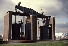
An 1817 Boulton & Watt beamblowing engine, used in Netherton at the ironworks of M W Grazebrook. Re-erected on the A38(M) in Birmingham, UK
                                                                       
 
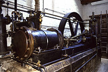
                                                      A mill engine from Stott Park Bobbin Mill, Cumbria, England
                                                                       
 
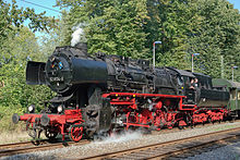
                      A steam locomotive from East Germany. This class of engine was built in 1942–1950 and operated until 1988.


Contents


History[edit]


Since the early 18th century, steam power has been applied to a variety of practical uses. At first it was applied to reciprocating pumps, but from the 1780s rotative engines (i.e. those converting reciprocating motion into rotary motion) began to appear, driving factory machinery such as spinning mules and power looms. At the turn of the 19th century, steam-powered transport on both sea and land began to make its appearance becoming ever more dominant as the century progressed.

Steam engines can be said to have been the moving force behind the Industrial Revolution and saw widespread commercial use driving machinery in factories, mills and mines; powering pumping stations; and propelling transport appliances such as railway locomotives, ships and road vehicles. Their use in agriculture led to an increase in the land available for cultivation.

The weight of boilers and condensors generally makes the power-to-weight ratio of a steam plant lower than for internal combustion engines. For mobile applications steam has been largely superseded by internal combustion engines or electric motors. However most electric power is generated using steam turbine plant, so that indirectly the world's industry is still dependent on steam power. Recent concerns about fuel sources and pollution have incited a renewed interest in steam both as a component of cogenerationprocesses and as a prime mover. This is becoming known as the Advanced Steam movement.

Early experiments[edit]

The history of the steam engine stretches back as far as the first century AD; the first recorded rudimentary steam engine being the aeolipile described by Greek mathematicianHero of Alexandria. In the following centuries, the few steam-powered "engines" known were, like the aeolipile, essentially experimental devices used by inventors to demonstrate the properties of steam. A rudimentary steam turbine device was described by Taqi al-Din in 1551 and by Giovanni Branca in 1629. Jerónimo de Ayanz y Beaumont received patents in 1606 for fifty steam powered inventions, including a water pump for draining inundated mines. Denis Papin, a Huguenot refugee, did some useful work on the steam digester in 1679, and first used a piston to raise weights in 1690.

Pumping engines[edit]

The first commercial steam-powered device was a water pump, developed in 1698 by Thomas Savery. It used a vacuum to raise water from below, then used steam pressure to raise it higher. Small engines were effective though larger models were problematic. They proved only to have a limited lift height and were prone to boiler explosions. It received some use in mines, pumping stations and for supplying water wheels used to power textile machinery. An attractive feature of the Savery engine was its low cost. It continued to be manufactured until the late 18th century. One engine was still known to be operating in 1820.

Piston steam engines[edit]


                                                                                    Jacob Leupold Steam engine 1720

The first commercially successful true engine, in that it could generate power and transmit it to a machine, was the atmospheric engine, invented by Thomas Newcomen around 1712.[18][19] It made use of technologies discovered by Savery and Papin. Newcomen's engine was relatively inefficient, and in most cases was used for pumping water. It worked by creating a partial vacuum by condensing steam under a piston within a cylinder. It was employed for draining mine workings at depths hitherto impossible, and also for providing a reusable water supply for driving waterwheels at factories sited away from a suitable "head". Water that had passed over the wheel was pumped back up into a storage reservoir above the wheel.[20]

In 1720 Jacob Leupold described a two-cylinder high-pressure steam engine.[21] The invention was published in his major work "Theatri Machinarum Hydraulicarum".[22] The engine used two lead-weighted pistons providing a continuous motion to a water pump. Each piston was raised by the steam pressure and returned to its original position by gravity. The two pistons shared a common four way rotary valve connected directly to a steam boiler.


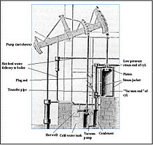
                                                                                              Early Watt pumping engine

The next major step occurred when James Watt developed (1763–1775) an improved version of Newcomen's engine, with a separate condenser. Boulton and Watt's early engines used half as much coal as John Smeaton's improved version of Newcomen's. Newcomen's and Watt's early engines were "atmospheric". They were powered by air pressure pushing a piston into the partial vacuum generated bycondensing steam, instead of the pressure of expanding steam. The engine cylinders had to be large because the only usable force acting on them was due to atmospheric pressure.

Watt proceeded to develop his engine further, modifying it to provide a rotary motion suitable for driving factory machinery. This enabled factories to be sited away from rivers, and further accelerated the pace of the Industrial Revolution.

High-pressure engines[edit]

Around 1800 Richard Trevithick and, separately, Oliver Evans in 1801 introduced engines using high-pressure steam; Trevithick obtained his high-pressure engine patent in 1802. These were much more powerful for a given cylinder size than previous engines and could be made small enough for transport applications. Thereafter, technological developments and improvements in manufacturing techniques (partly brought about by the adoption of the steam engine as a power source) resulted in the design of more efficient engines that could be smaller, faster, or more powerful, depending on the intended application.

The Cornish engine was developed by Trevithick and others in the 1810s. It was a compound cycle engine that used high-pressure steam expansively, then condensed the low-pressure steam, making it relatively efficient. The Cornish engine had irregular motion and torque though the cycle, limiting it mainly to pumping. Cornish engines were used in mines and for water supply until the late 19th century.

Horizontal stationary engine[edit]

Main article: Stationary steam engine

Early builders of stationary steam engines considered that horizontal cylinders would be subject to excessive wear. Their engines were therefore arranged with the piston axis vertical. In time the horizontal arrangement became more popular, allowing compact, but powerful engines to be fitted in smaller spaces.

The acme of the horizontal engine was the Corliss steam engine, patented in 1849, which was a four-valve counter flow engine with separate steam admission and exhaust valves and automatic variable steam cutoff. When introduced, it was called the most significant advance in the steam engine since James Watt. In addition to using 30% less steam, it provided more uniform speed due to variable steam cut off, making it well suited to manufacturing, especially cotton spinning.

Marine engines[edit]


                                              A triple expansion marine steam engine on the 1907 ocean going tugHercules
 

Near the end of the 19th century compound engines came into widespread use. Compound engines exhausted steam in to successively larger cylinders to accommodate the higher volumes at reduced pressures, giving improved efficiency. These stages were called expansions, with double and triple expansion engines being common, especially in shipping where efficiency was important to reduce the weight of coal carried.[20] Steam engines remained the dominant source of power until the early 20th century, when advances in the design of electric motors and internal combustion engines gradually resulted in the replacement of reciprocating (piston) steam engines, with shipping in the 20th-century relying upon the steam turbine.[4]

Steam locomotives[edit]

Main articles: Steam locomotive and Traction engine

As the development of steam engines progressed through the 18th century, various attempts were made to apply them to road and railway use.[30] In 1784, William Murdoch, a Scottish inventor, built a prototype steam road locomotive.[31] An early working model of a steam rail locomotive was designed and constructed by steamboat pioneer John Fitch in the United States probably during the 1780s or 1790s.[32] His steam locomotive used interior bladed wheels guided by rails or tracks.

The first full-scale working railway steam locomotive was built by Richard Trevithick in the United Kingdom and, on 21 February 1804, the world's first railway journey took place as Trevithick's unnamed steam locomotive hauled a train along the tramway from the Pen-y-darren ironworks, near Merthyr Tydfil to Abercynon in south Wales.[30][33][34] The design incorporated a number of important innovations that included using high-pressure steam which reduced the weight of the engine and increased its efficiency. Trevithick visited the Newcastle area later in 1804 and the colliery railways in north-east England became the leading centre for experimentation and development of steam locomotives.[35] Trevithick continued his own experiments using a trio of locomotives, concluding with the Catch Me Who Can in 1808. Only four years later, the successful twin-cylinder locomotiveSalamanca by Matthew Murray was used by the edge railed rack and pinion Middleton Railway.[36] In 1825 George Stephenson built the Locomotion for the Stockton and Darlington Railway. This was the first public steam railway in the world and then in 1829, he built The Rocket which was entered in and won the Rainhill Trials.[37] The Liverpool and Manchester Railway opened in 1830 making exclusive use of steam power for both passenger and freight trains.

Steam locomotives continued to be manufactured until the late twentieth century in places such as China and the former East Germany.[38]

Steam turbines[edit]

Main article: Steam turbine

The final major evolution of the steam engine design was the use of steam turbines starting in the late part of the 19th century. Steam turbines are generally more efficient than reciprocating piston type steam engines (for outputs above several hundred horsepower), have fewer moving parts, and provide rotary power directly instead of through aconnecting rod system or similar means.[39] Steam turbines virtually replaced reciprocating engines in electricity generating stations early in the 20th century, where their efficiency, higher speed appropriate to generator service, and smooth rotation were advantages. Today most electric power is provided by steam turbines. In the United States 90% of the electric power is produced in this way using a variety of heat sources.[4] Steam turbines were extensively applied for propulsion of large ships throughout most of the 20th century.

Present development[edit]

Main article: Advanced steam technology

Although the reciprocating steam engine is no longer in widespread commercial use, various companies are exploring or exploiting the potential of the engine as an alternative to internal combustion engines. The company Energiprojekt AB in Sweden has made progress in using modern materials for harnessing the power of steam. The efficiency of Energiprojekt's steam engine reaches some 27-30% on high-pressure engines. It is a single-step, 5-cylinder engine (no compound) with superheated steam and consumes approx. 4 kg (8.8 lb) of steam per kWh.[40]

Components and accessories of steam engines[edit]

There are two fundamental components of a steam plant: the boiler or steam generator, and the "motor unit", referred to itself as a "steam engine". Stationary steam engines in fixed buildings may have the boiler and engine in separate buildings some distance apart. For portable or mobile use, such as steam locomotives, the two are mounted together.[41][42]

The widely used reciprocating engine typically consisted of a cast iron cylinder, piston, connecting rod and beam or a crank and flywheel, and miscellaneous linkages. Steam was alternately supplied and exhausted by one or more valves. Speed control was either automatic, using a governor, or by a manual valve. The cylinder casting contained steam supply and exhaust ports.

Engines equipped with a condenser are a separate type than those that exhaust to the atmosphere.

Other components are often present; pumps (such as an injector) to supply water to the boiler during operation, condensers to recirculate the water and recover the latent heat of vaporisation, and superheaters to raise the temperature of the steam above its saturated vapour point, and various mechanisms to increase the draft for fireboxes. When coal is used, a chain or screw stoking mechanism and its drive engine or motor may be included to move the fuel from a supply bin (bunker) to the firebox.[43] See: Mechanical stoker

Heat source[edit]

The heat required for boiling the water and supplying the steam can be derived from various sources, most commonly from burning combustible materials with an appropriate supply of air in a closed space (called variously combustion chamber, firebox). In some cases the heat source is a nuclear reactor or geothermal energy.

Boilers[edit]

Main article: Boiler (steam generator)
 
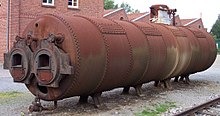
An industrial boiler used for a stationary steam engine

Boilers are pressure vessels that contain water to be boiled, and some kind of mechanism for transferring the heat to the water so as to boil it.[44]

The two most common methods of transferring heat to the water are:

  1. water-tube boiler – water is contained in or run through one or several tubes surrounded by hot gases
  2. fire-tube boiler – the water partially fills a vessel below or inside which is a combustion chamber or furnace and fire tubes through which the hot gases flow

Fire tube boilers were the main type used for early high-pressure steam (typical steam locomotive practice), but they were to a large extent displaced by more economical water tube boilers in the late 19th century for marine propulsion and large stationary applications.

Once turned to steam, many boilers raise the temperature of the steam further, turning 'wet steam' into 'superheated steam'. This use of superheating avoids the steam condensing within the engine, and allows significantly greater efficiency.[45]

Motor units[edit]

For more details on this topic, see Types of motor units (below)

A motor unit[citation needed] takes a supply of steam at high pressure and temperature and gives out a supply of steam at lower pressure and temperature, using as much of the difference in steam energy as possible to do mechanical work. Motor units are typically a type of piston or steam turbine.

A motor unit is often called 'steam engine' in its own right. They will also operate on compressed air or other gas.[citation needed]

Cold sink[edit]

 
A power station's cooling tower produces clouds from the condensing water vapor due to evaporated cooling water.

As with all heat engines, a considerable quantity of waste heat at relatively low temperature is produced and must be disposed of.

The simplest cold sink is to vent the steam to the environment. This is often used on steam locomotives, as the released steam is released in the chimney so as to increase the draw on the fire, which greatly increases engine power, but is inefficient. Condensing steam locomotives have been built, but only for special applications such as working in tunnels and where supplies of water are scarce.[citation needed]

Sometimes the waste heat is useful itself, and in those cases very high overall efficiency can be obtained. For example, combined heat and power (CHP) systems use the waste steam for district heating.[citation needed]

Where CHP is not used, steam turbines in power stations use surface condensers as a cold sink. The condensers are cooled by water flow from oceans, rivers, lakes, and often by cooling towers which evaporate water to provide cooling energy removal. The resulting condensed hot water output from the condenser is then put back into the boiler via a pump. A dry type cooling tower is similar to an automobile radiator and is used in locations where water is costly. Evaporative (wet) cooling towers use the rejected heat to evaporate water; this water is kept separate from the condensate, which circulates in a closed system and returns to the boiler. Such towers often have visible plumes due to the evaporated water condensing into droplets carried up by the warm air. Evaporative cooling towers need less water flow than "once-through" cooling by river or lake water; a 700 megawatt coal-fired power plant may use about 3600 cubic metres of make-up water every hour for evaporative cooling, but would need about twenty times as much if cooled by river water.[citation needed]

 
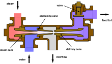
An injector uses a jet of steam to force water into the boiler. Injectors are inefficient but simple enough to be suitable for use on locomotives.

Water pump[edit]

The Rankine cycle and most practical steam engines have a water pump to recycle or top up the boiler water, so that they may be run continuously. Utility and industrial boilers commonly use multi-stage centrifugal pumps; however, other types are used. Another means of supplying lower-pressure boiler feed water is an injector, which uses a steam jet usually supplied from the boiler. Injectors became popular in the 1850s but are no longer widely used, except in applications such as steam locomotives.[46]

Monitoring and control[edit]

 
Richard's indicator instrument of 1875. See: Indicator diagram (below)

For safety reasons, nearly all steam engines are equipped with mechanisms to monitor the boiler, such as a pressure gauge and a sight glass to monitor the water level.

Many engines, stationary and mobile, are also fitted with a governor (see below) to regulate the speed of the engine without the need for human interference (similar to cruise control in some cars).

The most useful instrument for analyzing the performance of steam engines is the steam engine indicator. Early versions were in use by 1851,[47] but the most successful indicator was developed for the high speed engine inventor and manufacturer Charles Porter by Charles Richard and exhibited at London Exhibition in 1862.[25] The steam engine indicator traces on paper the pressure in the cylinder throughout the cycle, which can be used to spot various problems and calculate developed horsepower.[48] It was routinely used by engineers, mechanics and insurance inspectors. The engine indicator can also be used on internal combustion engines. See image of indicator diagram below (in Types of motor units section).

 
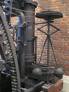
Centrifugal governor in a Boulton & Watt engine of 1788.

Governor[edit]

Main article: Governor (device)

The centrifugal governor was adopted by James Watt for use on a steam engine in 1788 after Watt’s partner Boulton saw one at a flour millBoulton & Watt were building.[49] The governor could not actually hold a set speed, because it would assume a new constant speed in response to load changes. The governor was able to handle smaller variations such as those caused by fluctuating heat load to the boiler. Also, there was a tendency for oscillation whenever there was a speed change. As a consequence, engines equipped only with this governor were not suitable for operations requiring constant speed, such as cotton spinning.[50] The governor was improved over time and coupled with variable steam cut off, good speed control in response to changes in load was attainable near the end of the 19th century.

Engine configuration[edit]


Simple engine[edit]

In a simple engine the charge of steam works only once in a cylinder.[51] It is then exhausted directly into the atmosphere or into a condenser. As steam expands in a high-pressure engine its temperature drops because no heat is added to the system; this is known asadiabatic expansion and results in steam entering the cylinder at high temperature and leaving at low temperature. This causes a cycle of heating and cooling of the cylinder with every stroke, which is a source of inefficiency.[52]

Compound engines

Main article: Compound engine

A method to lessen the magnitude of this heating and cooling was invented in 1804 by British engineer Arthur Woolf, who patented hisWoolf high-pressure compound engine in 1805. In the compound engine, high-pressure steam from the boiler expands in a high-pressure (HP) cylinder and then enters one or more subsequent lower-pressure (LP) cylinders. The complete expansion of the steam now occurs across multiple cylinders and as less expansion now occurs in each cylinder less heat is lost by the steam in each. This reduces the magnitude of cylinder heating and cooling, increasing the efficiency of the engine. By staging the expansion in multiple cylinders, torque variability can be reduced. To derive equal work from lower-pressure steam requires a larger cylinder volume as this steam occupies a greater volume. Therefore the bore, and often the stroke, are increased in low-pressure cylinders resulting in larger cylinders.[20]

Double expansion (usually known as compound) engines expanded the steam in two stages. The pairs may be duplicated or the work of the large low-pressure cylinder can be split with one high-pressure cylinder exhausting into one or the other, giving a 3-cylinder layout where cylinder and piston diameter are about the same making the reciprocating masses easier to balance.[20]

Two-cylinder compounds can be arranged as:

  • Cross compounds – The cylinders are side by side.
  • Tandem compounds – The cylinders are end to end, driving a common connecting rod
  • Angle compounds – The cylinders are arranged in a vee (usually at a 90° angle) and drive a common crank.

With two-cylinder compounds used in railway work, the pistons are connected to the cranks as with a two-cylinder simple at 90° out of phase with each other (quartered). When the double expansion group is duplicated, producing a 4-cylinder compound, the individual pistons within the group are usually balanced at 180°, the groups being set at 90° to each other. In one case (the first type of Vauclain compound), the pistons worked in the same phase driving a common crosshead and crank, again set at 90° as for a two-cylinder engine. With the 3-cylinder compound arrangement, the LP cranks were either set at 90° with the HP one at 135° to the other two, or in some cases all three cranks were set at 120°.[citation needed]

The adoption of compounding was common for industrial units, for road engines and almost universal for marine engines after 1880; it was not universally popular in railway locomotives where it was often perceived as complicated. This is partly due to the harsh railway operating environment and limited space afforded by the loading gauge(particularly in Britain, where compounding was never common and not employed after 1930). However, although never in the majority, it was popular in many other countries.[53]

Multiple expansion engines[edit]


Main article: Compound engine
 
An animation of a simplified triple-expansion engine.
High-pressure steam (red) enters from the boiler and passes through the engine, exhausting as low-pressure steam (blue), usually to a condenser.

It is a logical extension of the compound engine (described above) to split the expansion into yet more stages to increase efficiency. The result is the multiple expansion engine. Such engines use either three or four expansion stages and are known as triple and quadruple expansion engines respectively. These engines use a series of cylinders of progressively increasing diameter. These cylinders are designed to divide the work into equal shares for each expansion stage. As with the double expansion engine, if space is at a premium, then two smaller cylinders may be used for the low-pressure stage. Multiple expansion engines typically had the cylinders arranged inline, but various other formations were used. In the late 19th century, the Yarrow-Schlick-Tweedy balancing 'system' was used on some marine triple expansion engines. Y-S-T engines divided the low-pressure expansion stages between two cylinders, one at each end of the engine. This allowed the crankshaft to be better balanced, resulting in a smoother, faster-responding engine which ran with less vibration. This made the 4-cylinder triple-expansion engine popular with large passenger liners (such as the Olympic class), but this was ultimately replaced by the virtually vibration-free turbine (see below).[citation needed]

The image to the right shows an animation of a triple expansion engine. The steam travels through the engine from left to right. The valve chest for each of the cylinders is to the left of the corresponding cylinder.

Land-based steam engines could exhaust much of their steam, as feed water was usually readily available. Prior to and during World War I, the expansion engine dominated marine applications where high vessel speed was not essential. It was however superseded by the British invention steam turbine where speed was required, for instance in warships, such as the dreadnought battleships, and ocean liners. HMS Dreadnought of 1905 was the first major warship to replace the proven technology of the reciprocating engine with the then-novel steam turbine.[citation needed][54]

Types of motor units[edit]

Reciprocating piston[edit]

 
Double acting stationary engine. This was the common mill engine of the mid 19th century. Note the slide valve with concave, almost "D" shaped, underside.
 
Schematic Indicator diagram showing the four events in a double piston stroke. See: Monitoring and control (above)
Main article: Reciprocating engine

In most reciprocating piston engines, the steam reverses its direction of flow at each stroke (counterflow), entering and exhausting from the cylinder by the same port. The complete engine cycle occupies one rotation of the crank and two piston strokes; the cycle also comprises four events – admission, expansion, exhaust, compression. These events are controlled by valves often working inside a steam chest adjacent to the cylinder; the valves distribute the steam by opening and closing steam ports communicating with the cylinder end(s) and are driven by valve gear, of which there are many types.[citation needed]The simplest valve gears give events of fixed length during the engine cycle and often make the engine rotate in only one direction. Most however have a reversing mechanism which additionally can provide means for saving steam as speed and momentum are gained by gradually "shortening the cutoff" or rather, shortening the admission event; this in turn proportionately lengthens the expansion period. However, as one and the same valve usually controls both steam flows, a short cutoff at admission adversely affects the exhaust and compression periods which should ideally always be kept fairly constant; if the exhaust event is too brief, the totality of the exhaust steam cannot evacuate the cylinder, choking it and giving excessive compression ("kick back").[citation needed]

In the 1840s and 50s, there were attempts to overcome this problem by means of various patent valve gears with a separate, variable cutoff expansion valve riding on the back of the main slide valve; the latter usually had fixed or limited cutoff. The combined setup gave a fair approximation of the ideal events, at the expense of increased friction and wear, and the mechanism tended to be complicated. The usual compromise solution has been to provide lap by lengthening rubbing surfaces of the valve in such a way as to overlap the port on the admission side, with the effect that the exhaust side remains open for a longer period after cut-off on the admission side has occurred. This expedient has since been generally considered satisfactory for most purposes and makes possible the use of the simpler Stephenson, Joy and Walschaerts motions. Corliss, and later, poppet valve gears had separate admission and exhaust valves driven by trip mechanisms or cams profiled so as to give ideal events; most of these gears never succeeded outside of the stationary marketplace due to various other issues including leakage and more delicate mechanisms.[53][55]

Compression

Before the exhaust phase is quite complete, the exhaust side of the valve closes, shutting a portion of the exhaust steam inside the cylinder. This determines the compression phase where a cushion of steam is formed against which the piston does work whilst its velocity is rapidly decreasing; it moreover obviates the pressure and temperature shock, which would otherwise be caused by the sudden admission of the high-pressure steam at the beginning of the following cycle.[citation needed]

Lead

The above effects are further enhanced by providing lead: as was later discovered with the internal combustion engine, it has been found advantageous since the late 1830s to advance the admission phase, giving the valve lead so that admission occurs a little before the end of the exhaust stroke in order to fill the clearance volume comprising the ports and the cylinder ends (not part of the piston-swept volume) before the steam begins to exert effort on the piston.[56]

Uniflow (or unaflow) engine[edit]

 
Schematic animation of a uniflow steam engine.
The poppet valves are controlled by the rotating camshaft at the top. High-pressure steam enters, red, and exhausts, yellow.
Main article: Uniflow steam engine

Uniflow engines attempt to remedy the difficulties arising from the usual counterflow cycle where, during each stroke, the port and the cylinder walls will be cooled by the passing exhaust steam, whilst the hotter incoming admission steam will waste some of its energy in restoring working temperature. The aim of the uniflow is to remedy this defect and improve efficiency by providing an additional port uncovered by the piston at the end of each stroke making the steam flow only in one direction. By this means, the simple-expansion uniflow engine gives efficiency equivalent to that of classic compound systems with the added advantage of superior part-load performance, and comparable efficiency to turbines for smaller engines below one thousand horsepower. However, the thermal expansion gradient uniflow engines produce along the cylinder wall gives practical difficulties.[citation needed]

Turbine engines[edit]

 
A rotor of a modern steam turbine, used in a power plant
Main article: Steam turbine

A steam turbine consists of one or more rotors (rotating discs) mounted on a drive shaft, alternating with a series of stators (static discs) fixed to the turbine casing. The rotors have a propeller-like arrangement of blades at the outer edge. Steam acts upon these blades, producing rotary motion. The stator consists of a similar, but fixed, series of blades that serve to redirect the steam flow onto the next rotor stage. A steam turbine often exhausts into a surface condenser that provides a vacuum. The stages of a steam turbine are typically arranged to extract the maximum potential work from a specific velocity and pressure of steam, giving rise to a series of variably sized high- and low-pressure stages. Turbines are only efficient if they rotate at relatively high speed, therefore they are usually connected to reduction gearing to drive lower speed applications, such as a ship's propeller. In the vast majority of large electric generating stations, turbines are directly connected to generators with no reduction gearing. Typical speeds are 3600 revolutions per minute (RPM) in the USA with 60 Hertz power, 3000 RPM in Europe and other countries with 50 Hertz electric power systems. In nuclear power applications the turbines typically run at half these speeds, 1800 RPM and 1500 RPM. A turbine rotor is also only capable of providing power when rotating in one direction. Therefore a reversing stage or gearbox is usually required where power is required in the opposite direction.[citation needed]

Steam turbines provide direct rotational force and therefore do not require a linkage mechanism to convert reciprocating to rotary motion. Thus, they produce smoother rotational forces on the output shaft. This contributes to a lower maintenance requirement and less wear on the machinery they power than a comparable reciprocating engine.[citation needed]

 
Turbinia – the first steam turbine-powered ship

The main use for steam turbines is in electricity generation (in the 1990s about 90% of the world's electric production was by use of steam turbines)[4] however the recent widespread application of large gas turbine units and typical combined cycle power plants has resulted in reduction of this percentage to the 80% regime for steam turbines. In electricity production, the high speed of turbine rotation matches well with the speed of modern electric generators, which are typically direct connected to their driving turbines. In marine service, (pioneered on the Turbinia), steam turbines with reduction gearing (although the Turbinia has direct turbines to propellers with no reduction gearbox) dominated large ship propulsion throughout the late 20th century, being more efficient (and requiring far less maintenance) than reciprocating steam engines. In recent decades, reciprocating Diesel engines, and gas turbines, have almost entirely supplanted steam propulsion for marine applications.

Virtually all nuclear power plants generate electricity by heating water to provide steam that drives a turbine connected to an electrical generator. Nuclear-powered ships and submarines either use a steam turbine directly for main propulsion, with generators providing auxiliary power, or else employ turbo-electric transmission, where the steam drives a turbo generator set with propulsion provided by electric motors. A limited number of steam turbine railroad locomotives were manufactured. Some non-condensing direct-drive locomotives did meet with some success for long haul freight operations in Sweden and for express passenger work in Britain, but were not repeated. Elsewhere, notably in the U.S.A., more advanced designs with electric transmission were built experimentally, but not reproduced. It was found that steam turbines were not ideally suited to the railroad environment and these locomotives failed to oust the classic reciprocating steam unit in the way that modern diesel and electric traction has done.[citation needed]

 
Operation of a simple oscillating cylinder steam engine

Oscillating cylinder steam engine

An oscillating cylinder steam engine is a variant of the simple expansion steam engine which does not require valves to direct steam into and out of the cylinder. Instead of valves, the entire cylinder rocks, or oscillates, such that one or more holes in the cylinder line up with holes in a fixed port face or in the pivot mounting (trunnion). These engines are mainly used in toys and models, because of their simplicity, but have also been used in full size working engines, mainly on ships where their compactness is valued.[citation needed]

Rotary steam engines[edit]

It is possible to use a mechanism based on a pistonless rotary engine such as the Wankel engine in place of the cylinders and valve gearof a conventional reciprocating steam engine. Many such engines have been designed, from the time of James Watt to the present day, but relatively few were actually built and even fewer went into quantity production; see link at bottom of article for more details. The major problem is