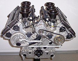
Simple machines, such as the club and oar (examples of the lever), are prehistoric. More complex engines using human power, animal power, water power, wind power and even steam power date back to antiquity. Human power was focused by the use of simple engines, such as the capstan, windlass or treadmill, and with ropes, pulleys, and block and tackle arrangements; this power was transmitted usually with the forces multiplied and the speed reduced. These were used in cranes and aboard ships in Ancient Greece, as well as in mines, water pumps and siege engines in Ancient Rome. The writers of those times, including Vitruvius, Frontinus and Pliny the Elder, treat these engines as commonplace, so their invention may be more ancient. By the 1st century AD, cattle and horses were used in mills, driving machines similar to those powered by humans in earlier times.
According to Strabo, a water powered mill was built in Kaberia of the kingdom of Mithridates during the 1st century BC. Use of water wheels in mills spread throughout the Roman Empire over the next few centuries. Some were quite complex, with aqueducts, dams, and sluices to maintain and channel the water, along with systems of gears, or toothed-wheels made of wood and metal to regulate the speed of rotation. More sophisticated small devices, such as the Antikythera Mechanism used complex trains of gears and dials to act as calendars or predict astronomical events. In a poem by Ausonius in the 4th century AD, he mentions a stone-cutting saw powered by water. Hero of Alexandria is credited with many such wind and steam powered machines in the 1st century AD, including the Aeolipile and the vending machine, often these machines were associated with worship, such as animated altars and automated temple doors.
Medieval Muslim engineers employed gears in mills and water-raising machines, and used dams as a source of water power to provide additional power to watermills and water-raising machines.[7] In the medieval Islamic world, such advances made it possible to mechanize many industrial tasks previously carried out by manual labour.
In 1206, al-Jazari employed a crank-conrod system for two of his water-raising machines. A rudimentary steam turbine device was described by Taqi al-Din[7] in 1551 and byGiovanni Branca[8] in 1629.[9]
In the 13th century, the solid rocket motor was invented in China. Driven by gunpowder, this, the simplest form of internal combustion engine was unable to deliver sustained power, but was useful for propelling weaponry at high speeds towards enemies in battle and for fireworks. After invention, this innovation spread throughout Europe.
The Watt steam engine was the first type of steam engine to make use of steam at a pressure just above atmospheric to drive the piston helped by a partial vacuum. Improving on the design of the 1712 Newcomen steam engine, the Watt steam engine, developed sporadically from 1763 to 1775, was a great step in the development of the steam engine. Offering a dramatic increase in fuel efficiency, James Watt's design became synonymous with steam engines, due in no small part to his business partner, Matthew Boulton. It enabled rapid development of efficient semi-automated factories on a previously unimaginable scale in places where waterpower was not available. Later development led to steam locomotivesand great expansion of railway transportation.
As for internal combustion piston engines, these were tested in France in 1807 by de Rivaz and independently, by the Niépce brothers . They were theoretically advanced by Carnot in 1824.[citation needed] In 1853-57 Eugenio Barsanti and Felice Matteucci invented and patented an engine using the free-piston principle that was possibly the first 4-cycle engine.[10] The Otto cycle in 1877 was capable of giving a far higher power to weight ratiothan steam engines and worked much better for many transportation applications such as cars and aircraft.
The first commercially successful automobile, created by Karl Benz, added to the interest in light and powerful engines. The lightweight petrol internal combustion engine, operating on a four-stroke Otto cycle, has been the most successful for light automobiles, while the more efficient Diesel engine is used for trucks and buses. However, in recent years, turbo Diesel engines have become increasingly popular, especially outside of the United States, even for quite small cars.
In 1896, Karl Benz was granted a patent for his design of the first engine with horizontally opposed pistons. His design created an engine in which the corresponding pistons move in horizontal cylinders and reach top dead center simultaneously, thus automatically balancing each other with respect to their individual momentum. Engines of this design are often referred to as flat engines because of their shape and lower profile. They are or were used in: the Volkswagen Beetle, some Porsche and Subaru cars, many BMW andHonda motorcycles, and aircraft engines (for propeller driven aircraft), etc.
The first half of the 20th century saw a trend to increasing engine power, particularly in the American models[clarification needed]. Design changes incorporated all known methods of raising engine capacity, including increasing the pressure in the cylinders to improve efficiency, increasing the size of the engine, and increasing the speed at which power is generated. The higher forces and pressures created by these changes created engine vibration and size problems that led to stiffer, more compact engines with V and opposed cylinder layouts replacing longer straight-line arrangements.
The design principles favoured in Europe, because of economic and other restraints such as smaller and twistier roads, leant toward smaller cars and corresponding to the design principles that concentrated on increasing the combustion efficiency of smaller engines. This produced more economical engines with earlier four-cylinder designs rated at 40 horsepower (30 kW) and six-cylinder designs rated as low as 80 horsepower (60 kW), compared with the large volume V-8 American engines with power ratings in the range from 250 to 350 hp, some even over 400 hp (190 to 260 kW).[clarification needed][citation needed]
Earlier automobile engine development produced a much larger range of engines than is in common use today. Engines have ranged from 1- to 16-cylinder designs with corresponding differences in overall size, weight, engine displacement, and cylinder bores. Four cylinders and power ratings from 19 to 120 hp (14 to 90 kW) were followed in a majority of the models. Several three-cylinder, two-stroke-cycle models were built while most engines had straight or in-line cylinders. There were several V-type models and horizontally opposed two- and four-cylinder makes too. Overhead camshafts were frequently employed. The smaller engines were commonly air-cooled and located at the rear of the vehicle; compression ratios were relatively low. The 1970s and 1980s saw an increased interest in improved fuel economy, which caused a return to smaller V-6 and four-cylinder layouts, with as many as five valves per cylinder to improve efficiency. The Bugatti Veyron 16.4 operates with a W16 engine, meaning that two V8 cylinder layouts are positioned next to each other to create the W shape sharing the same crankshaft.
The largest internal combustion engine ever built is the Wärtsilä-Sulzer RTA96-C, a 14-cylinder, 2-stroke turbocharged diesel engine that was designed to power the Emma Mærsk, the largest container ship in the world. This engine weighs 2,300 tons, and when running at 102 RPM produces 109,000 bhp (80,080 kW) consuming some 13.7 tons of fuel each hour.
nternal combustion engines are one of the building blocks of modern civilization. In an internal combustion engine, the combustion takes place inside a confined chamber. All internal combustion engines burn a mixture of air & fuel. The fuel can be gasoline, diesel, methane, propane etc.
The piston is the heart of an internal combustion engine..The concept of the piston engine is that a supply of air-and-fuel mixture is fed to the inside of the cylinder where it is compressed and then burnt. This internal combustion releases heat energy which is then converted into useful mechanical work as the high gas pressures generated force the piston to move along its stroke in the cylinder. It can be said, therefore, that a heat-engine is merely an energy transformer.
To enable the piston movement to be harnessed, the driving thrust on the piston is transmitted by means of a connecting-rod to a crankshaft whose function is to convert the linear piston motion in the cylinder to a rotary crankshaft movement (Fig. 1.1-1). The piston can thus be made to repeat its movement to and fro, due to the constraints of the crankshaft crankpin’s circular path and the guiding cylinder.

he backward-and-forward displacement of the piston is generally referred to as the reciprocating motion of the piston, so these power units are also known as reciprocating engines.
Identification of major engine components makes it easier to understand its working principle. Some major engine components are, cylinder block, piston, piston rings, connecting-rod, cylinder head, crankcase, crankshaft etc. The following briefly describes the major engine components and some terms associated with them. (Figs. 1.1-1 and 1.1-2).
Cylinder block This is a cast structure with cylindrical holes bored to guide and support the pistons and to harness the working gases. It also provides a jacket to contain a liquid coolant.

Cylinder head This casting encloses the combustion end of the cylinder block and houses both the inlet and exhaust poppet-valves and their ports to admit air- fuel mixture and to exhaust the combustion products.
Crankcase This is a cast rigid structure which supports and houses the crankshaft and bearings. It is usually cast as a mono-construction with the cylinder block.
Sump This is a pressed-steel or cast-aluminum-alloy container which encloses the bottom of the crank-case and provides a reservoir for the engine's lubricant.
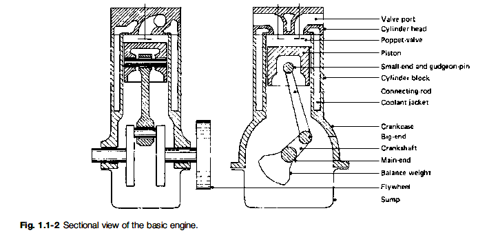
Piston This is a pressure-tight cylindrical plunger which is subjected to the expanding gas pressure. Its function is to convert the gas pressure from combustion into a concentrated driving thrust along the connecting-rod. It must therefore also act as a guide for the small-end of the connecting-rod.
Piston rings These are circular rings which seal the gaps made between the piston and the cylinder, their object being to prevent gas escaping and to control the amount of lubricant which is allowed to reach the top of the cylinder.
Gudgeon-pin This pin transfers the thrust from the piston to the connecting-rod small-end while permitting the rod to rock to and fro as the crankshaft rotates.
Connecting-rod This acts as both a strut and a tie link-rod. It transmits the linear pressure impulses acting on the piston to the crankshaft big-end journal, where they are converted into turning-effort.
Crankshaft A simple crankshaft consists of a circular-sectioned shaft which is bent or cranked to form two perpendicular crank-arms and an offset big-end journal. The unbent part of the shaft provides the main journals. The crankshaft is indirectly linked by the connecting-rod to the piston - this enables the straight-line motion of the piston to be transformed into a rotary motion at the crankshaft about the main-journal axis.
Crankshaft journals These are highly finished cylindrical pins machined parallel on both the centre axes and the offset axes of the crankshaft. When assembled, these journals rotate in plain bush-type bearings mounted in the crankcase (the main journals) and in one end of the connecting-rod (the big-end journal).
Small-end This refers to the hinged joint made by the gudgeon-pin between the piston and the connecting-rod so that the connecting-rod is free to oscillate relative to the cylinder axis as it moves to and fro in the cylinder.
Big-end This refers to the joint between the connecting-rod and the crankshaft big-end journal which provides the relative angular movement between the two components as the engine rotates.
Main-ends This refers to the rubbing pairs formed between the crankshaft main journals and their respective plain bearings mounted in the crankcase.
Line of stroke The centre path the piston is forced to follow due to the constraints of the cylinder is known as the line of stroke.
Inner and outer dead centers When the crank arm and the connecting-rod are aligned along the line of stroke, the piston will be in either one of its two extreme positions. If the piston is at its closest position to the cylinder head, the crank and piston are said to be at inner dead centre (IDC) or top dead centre (TDC). With the piston at its furthest position from the cylinder head, the crank and piston are said to be at outer dead centre (ODC) or bottom dead centre (BDC). These reference points are of considerable importance for valve-to-crankshaft timing and for either ignition or injection settings.
Clearance volume The space between the cylinder head and the piston crown at TDC is known as the clearance volume or the combustion-chamber space.
Crank-throw The distance from the centre of the crankshaft main journal to the centre of the big-end journal is known as the crank-throw. This radial length influences the leverage the gas pressure acting on the piston can apply in rotating the crankshaft.
Piston stroke The piston movement from IDC to ODC is known as the piston stroke and corresponds to the crankshaft rotating half a revolution or 180°. It is also equal to twice the crank-throw.
i.e. L = 2R
where L = piston stroke and R = crank-throw
Thus a long or short stroke will enable a large or small turning-effort to be applied to the crankshaft respectively.
Cylinder bore The cylinder block is initially cast with sand cores occupying the cylinder spaces. After the sand cores have been removed, the rough holes are machined with a single-point cutting tool attached radially at the end of a rotating bar. The removal of the unwanted metal in the hole is commonly known as boring the cylinder to size. Thus the finished cylindrical hole is known as the cylinder bore, and its internal diameter simply as the bore or bore size.
The history of diesel engine started with Herbert Akroyd-Stuart or Rudolf Diesel, who contributed most to the instigation and evolution of the high-speed compression-ignition (C.I.) engine burning heavy fuel oil. A brief summary of the background and achievements of these two pioneers is as follows.
Herbert Akroyd-Stuart, born 1864, was trained as an engineer in his father's works at Fenny Stratford, England. Between 1885 and 1890 he took out several patents for improvements to oil engines, and later, in conjunction with a Charles R. Binney of London, he took out patent number 7146 of 1890 describing the operation of his engine. Air alone was drawn into the cylinder and compressed into a separate combustion chamber (known as the vaporiser) through a contracted passage or bottleneck. A liquid fuel spray was then injected into the compressed air near the end of the compression stroke by means of a pump and a spraying nozzle. The combination of the hot chamber and the rise in temperature of the compressed air provided automatic ignition and rapid combustion at nearly constant volume - a feature of the C.I. engines of today.
These early engines were of low compression, the explosion taking place mainly due to the heat of the vaporizer chamber itself so that these engines became known as 'hot-bulb' or 'surface-ignition' engines. At starting, the separate combustion chamber was heated externally by an oil-lamp until the temperature attained was sufficient to ignite a few charges by compression. Then the chamber was maintained at a high enough temperature by the heat retained from the explosion together with the heat of the compressed air.
Rudolf Diesel was born in Paris in 1858, of German parents, and was educated at Augsburg and Munich. His works training was with Gebru¨-der Sulzer in Winterthur. Dr Diesel's first English patent, number 7421, was dated 1892 and was for an engine working on the ideal Carnot cycle and burning all kinds of fuel - solid, liquid, and gas - but the practical difficulties of achieving this ther-modynamic cycle proved to be far too much. A reliable diesel oil engine was built in 1897 after four years of experimental work in the Mashinen-fabrik Augsburg Nu¨rnberg (MAN) workshops.
In this engine, air was drawn into the cylinder and was compressed to 35-40 bar. Towards the end of the compression stroke, an air blast was introduced into the combustion space at a much higher pressure, about 68-70 bar, thus causing turbulence in the combustion chamber. A three-stage compressor driven by the engine (and consuming about 15% of the engine's gross power) supplied compressed air which was stored in a reservoir. This compressed air served both for starting the engine and for air-injection into the compressed air already in the cylinder - that is, for blasting air to atomize the oil fuel by forcing it through perforated discs fitted around a fluted needle-valve injector. The resulting finely divided oil mist ignites at once when it contacts the hot compressed cylinder air, and the burning rate then tends to match the increasing cylinder volume as the piston moves outwards - expansion will therefore take place at something approaching constant pressure.
A summary of the combustion processes of Akroyd-Stuart and Diesel is that the former inventor used a low compression-ratio, employed airless liquid-fuel injection, and relied on the hot combustion chamber to vaporize and ignite the fuel; whereas Diesel employed a relatively high compression-ratio, adopted air-injection to atomize the fuel, and made the hot turbulent air initiate burning. It may be said that the modern high-speed C.I. engine embraces both approaches in producing sparkles automatic combustion - combustion taking place with a combined process of constant volume and constant pressure known as either the mixed or the dual cycle.
Comparison of S.I. and C.I. engines is made from various aspects is made below:
Fuel economy The chief comparison to be made between the two types of engine is how effectively each engine can convert the liquid fuel into work energy. Different engines are compared by their thermal efficiencies. Thermal efficiency is the ratio of the useful work produced to the total energy supplied. Petrol engines can have thermal efficiencies ranging between 20% and 30%. The corresponding diesel engines generally have improved efficiencies, between 30% and 40%. Both sets of efficiency values are considerably influenced by the chosen compression-ratio and design.
Power and torque The petrol engine is usually designed with a shorter stroke and operates over a much larger crankshaft-speed range than the diesel engine. This enables more power to be developed towards the upper speed range in the petrol engine, which is necessary for high road speeds; however, a long-stroke diesel engine has improved pulling torque over a relatively narrow speed range, this being essential for the haulage of heavy commercial vehicles.
At the time of writing, there was a trend to incorporate diesel engines into cars. This new generation of engines has different design parameters and therefore does not conform to the above observations.
Reliability Due to their particular process of combustion, diesel engines are built sturdier, tend to run cooler, and have only half the speed range of most petrol engines. These factors make the diesel engine more reliable and considerably extend engine life relative to the petrol engine.
Pollution Diesel engines tend to become noisy and to vibrate on their mountings as the operating load is reduced. The combustion process is quieter in the petrol engine and it runs smoother than the diesel engine. There is no noisy injection equipment used on the petrol engine, unlike that necessary on the diesel engine. The products of combustion coming out of the exhaust system are more noticeable with diesel engines, particularly if any of the injection equipment components are out of tune. It is questionable which are the more harmful: the relatively invisible exhaust gases from the petrol engine, which include nitrogen dioxide, or the visible smoky diesel exhaust gases.
Safety Unlike petrol, diesel fuels are not flammable at normal operating temperature, so they are not a handling hazard and fire risks due to accidents are minimized.
Cost Due to their heavy construction and injection equipment, diesel engines are more expensive than petrol engines.
When the piston moves from one end of the cylinder to the other, it will sweep or displace air equal to the cylinder volume between TDC and BDC. Thus the full stroke movement of the piston is known as either the swept volume or the piston displacement.
The swept or displaced volume may be calculated as follows:
pd2L V ¼ 4000
where V ¼ piston displacement (cm3)
p ¼ 3:142
d ¼ cylinder diameter (mm) and L ¼ cylinder stroke (mm)
Mean Effective Pressure
Mean effective pressure is an important term for measuring engine performance.The cylinder pressure varies considerably while the gas expands during the power stroke. Peak pressure will occur just after TDC, but this will rapidly drop as the piston moves towards BDC. When quoting cylinder pressure, it is therefore more helpful to refer to the average or mean effective pressure throughout the whole power stroke. The units used for mean effective pressure may be either kilo Newton per square meter (kN/m2) or bars (note: 1 bar ¼ 100 kN/m2).
Engine Torque
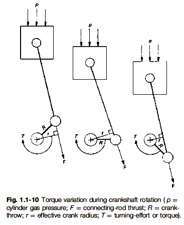
This is the turning-effort about the crankshaft's axis of rotation and is equal to the product of the force acting along the connecting-rod and the perpendicular distance between this force and the centre of rotation of the crankshaft. It is expressed in Newton meters (N m);
i.e. T = Fr
where T = engine torque (N m), F = force applied to crank (N) and r = effective crank-arm radius (m)
During the 180° crankshaft movement on the power stroke from TDC to BDC, the effective radius of the crank-arm will increase from zero at the top of its stroke to a maximum in the region of mid-stroke and then decrease to zero again at the end of its downward movement (Fig. 1.1-10). This implies that the torque on the power stroke is continually varying. Also, there will be no useful torque during the idling strokes. In fact some of the torque on the power stroke will be cancelled out in overcoming compression resistance and pumping losses, and the torque quoted by engine manufacturers is always the average value throughout the engine cycle.
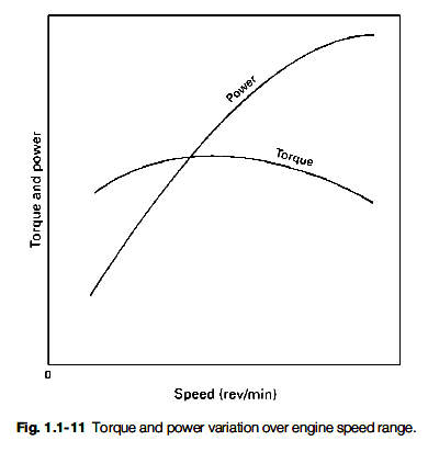
The average torque developed will vary over the engine's speed range. It reaches a maximum at about mid-speed and decreases on either side (Fig. 1.1-11).
Engine power
Power is the rate of doing work. When applied to engines, power ratings may be calculated either on the basis of indicated power (i.p.), that is the power actually developed in the cylinder, or on the basis of brake power (b.p.), which is the output power measured at the crankshaft. The b.p. is always less than the i.p., due to frictional and pumping losses in the cylinders and the reciprocating mechanism of the engine.
Since the rate of doing work increases with piston speed, the engine's power will tend to rise with crankshaft speed of rotation, and only after about two-thirds of the engine's speed range will the rate of power rise drop off (Fig. 1.1-11).
The slowing down and even decline in power at the upper speed range is mainly due to the very short time available for exhausting and for inducing fresh charge into the cylinders at very high speeds, with a resulting reduction in the cylinders' mean effective pressures.
Different countries have adopted their own standardized test procedures for measuring engine performance, so slight differences in quoted output figures will exist. Quoted performance figures should therefore always state the standard used. The three most important standards are those of the American Society of Automotive Engineers (SAE), the German Deutsch Industrie Normale (DIN), and the Italian Commissione technica di Unificazione nell Automobile (CUNA).
The two methods of calculating power can be expressed as follows:
pLANn i:p: ¼ 60000
where i.p. ¼ indicated power (kW)
p ¼ effective pressure (kN/m2)
L ¼ length of stroke (m)
A ¼ cross-sectional area of piston (m2)
N ¼ crankshaft speed (rev/min)
and n ¼ number of cylinders
2pTN b:p: ¼ 60000
where b.p. ¼ brake power (kW)
p ¼ 3.142
T ¼engine torque (N m) and N ¼ crankshaft speed (rev/min)
The imperial power is quoted in horsepower (hp) and is defined in terms of foot pounds per minute. In imperial units one horsepower is equivalent to 33 000 ft lb per minute or 550 ft lb per second. A metric horsepower is defined in terms of Newton-meters per second and is equal to 0.986 imperial horsepower. In Germany the abbreviation for horsepower is PS derived from the translation of the words 'Pferd-St¨arke' meaning horse strength.
The international unit for power is the watt, W, or more usually the kilowatt, kW, where 1 kW ¼ 1000 W.
Conversion from watt to horsepower and vice versa is: 1 kW ¼ 1.35 hp and 1 hp ¼ 0.746 kW
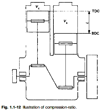
Compression-ratio is a very important parameter for measuring engine performance.The compression-ratio may be defined as the ratio of the maximum cylinder volume when the piston is at its outermost position (BDC) to the minimum cylinder volume (the clearance volume) with the piston at its innermost position (TDC) - that is, the sum of the swept and clearance volumes divided by the clearance volume,
Vs þVc i:e: CR ¼ Vc
where CR ¼ compression ratio
Vs ¼ swept volume (cm3) Vc ¼ clearance volume (cm3)
Petrol engines have compression-ratios of the order of 7:1 to 10:1; but, to produce self-ignition of the charge, diesel engines usually double these figures and may have values of between 14:1 and 24:1 for naturally aspirated (depression-induced filling) types, depending on the design.
In an engine cylinder, the gas molecules are moving about at considerable speed in the space occupied by the gas, colliding with other molecules and the boundary surfaces of the cylinder head, the cylinder walls, and the piston crown. The rapid succession of impacts of many millions of molecules on the boundary walls produces a steady continuous force per unit surface which is known as pressure (Fig. 1.1-12).
When the gas is compressed into a much smaller space, the molecules are brought closer to one another. This raises the temperature and greatly increases the speed of the molecules and hence their kinetic energy, so more violent impulses will impinge on the piston crown. This increased activity of the molecules is experienced as increased opposition to movement of the piston towards the cylinder head.
The process of compressing a constant mass of gas into a much smaller space enables many more molecules to impinge per unit area on to the piston. When burning of the gas occurs, the chemical energy of combustion is rapidly transformed into heat energy which considerably increases the kinetic energy of the closely packed gas molecules. Therefore the extremely large number of molecules squeezed together will thus bombard the piston crown at much higher speeds. This then means that a very large number of repeated blows of considerable magnitude will strike the piston and so push it towards ODC.
This description of compression, burning, and expansion of the gas charge shows the importance of utilising a high degree of compression before burning takes place, to improve the efficiency of combustion. The amount of compression employed in the cylinder is measured by the reduction in volume when the piston moves from BDC to TDC, the actual proportional change in volume being expressed as the compression-ratio.
Sri neelakanteswara ITI


