

Understanding how diesel engines are controlled and the types of protective instrumentation available is important for a complete understanding of the operation of a diesel engine.
The control of a diesel engine is accomplished through several components: the camshaft, the fuel injector, and the governor. The camshaft provides the timing needed to properly inject the fuel, the fuel injector provides the component that meters and injects the fuel, and the governor regulates the amount of fuel that the injector is to inject. Together, these three major components ensure that the engine runs at the desired speed.
Each cylinder has a fuel injector designed to meter and inject fuel into the cylinder at the proper instant. To accomplish this function, the injectors are actuated by the engine's camshaft. The camshaft provides the timing and pumping action used by the injector to inject the fuel. The injectors meter the amount of fuel injected into the cylinder on each stroke. The amount of fuel to be injected by each injector is set by a mechanical linkage called the fuel rack. The fuel rack position is controlled by the engine's governor. The governor determines the amount of fuel required to maintain the desired engine speed and adjusts the amount to be injected by adjusting the position of the fuel rack.
Each injector operates in the following manner. As illustrated in Figure 1, fuel under pressure enters the injector through the injector's filter cap and filter element. From the filter element the fuel travels down into the supply chamber (that area between the plunger bushing and the spill deflector). The plunger operates up and down in the bushing, the bore of which is open to the fuel supply in the supply chamber by two funnel-shaped ports in the plunger bushing.

The motion of the injector rocker arm (not shown) is transmitted to the plunger by the injector follower which bears against the follower spring. As the plunger moves downward under pressure of the injector rocker arm, a portion of the fuel trapped under the plunger is displaced into the supply chamber through the lower port until the port is closed off by the lower end of the plunger. The fuel trapped below the plunger is then forced up through the central bore of the plunger and back out the upper port until the upper port is closed off by the downward motion of the plunger. With the upper and lower ports both closed off, the remaining fuel under the plunger is subjected to an increase in pressure by the downward motion of the plunger.
When sufficient pressure has built up, the injector valve is lifted off its seat and the fuel is forced through small orifices in the spray tip and atomized into the combustion chamber. A check valve, mounted in the spray tip, prevents air in the combustion chamber from flowing back into the fuel injector. The plunger is then returned back to its original position by the injector follower spring.
On the return upward movement of the plunger, the high pressure cylinder within the bushing is again filled with fresh fuel oil through the ports. The constant circulation of fresh, cool fuel through the injector renews the fuel supply in the chamber and helps cool the injector. The fuel flow also effectively removes all traces of air that might otherwise accumulate in the system.
The fuel injector outlet opening, through which the excess fuel returns to the fuel return manifold and then back to the fuel tank, is adjacent to the inlet opening and contains a filter element exactly the same as the one on the fuel inlet side.
In addition to the reciprocating motion of the plunger, the plunger can be rotated during operation around its axis by the gear which meshes with the fuel rack. For metering the fuel, an upper helix and a lower helix are machined in the lower part of the plunger. The relation of the helices to the two ports in the injector bushing changes with the rotation of the plunger.
Changing the position of the helices, by rotating the plunger, retards or advances the closing of the ports and the beginning and ending of the injection period. At the same time, it increases or decreases the amount of fuel injected into the cylinder. Figure 2 illustrates the various plunger positions from NO LOAD to FULL LOAD. With the control rack pulled all the way (no injection), the upper port is not closed by the helix until after the lower port is uncovered. Consequently, with the rack in this position, all of the fuel is forced back into the supply chamber and no injection of fuel takes place. With the control rack pushed all the way in (full injection), the upper port is closed shortly after the lower port has been covered, thus producing a maximum effective stroke and maximum fuel injection. From this no-injection position to the full-injection position (full rack movement), the contour of the upper helix advances the closing of the ports and the beginning of injection.

Diesel engine speed is controlled solely by the amount of fuel injected into the engine by the injectors. Because a diesel engine is not self-speed-limiting, it requires not only a means of changing engine speed (throttle control) but also a means of maintaining the desired speed. The governor provides the engine with the feedback mechanism to change speed as needed and to maintain a speed once reached.
A governor is essentially a speed-sensing device, designed to maintain a constant engine speed regardless of load variation. Since all governors used on diesel engines control engine speed through the regulation of the quantity of fuel delivered to the cylinders, these governors may be classified as speed-regulating governors. As with the engines themselves there are many types and variations of governors. In this module, only the common mechanical-hydraulic type governor will be reviewed.
The major function of the governor is determined by the application of the engine. In an engine that is required to come up and run at only a single speed regardless of load, the governor is called a constant-speed type governor. If the engine is manually controlled, or controlled by an outside device with engine speed being controlled over a range, the governor is called a variable-speed type governor. If the engine governor is designed to keep the engine speed above a minimum and below a maximum, then the governor is a speed-limiting type. The last category of governor is the load limiting type. This type of governor limits fuel to ensure that the engine is not loaded above a specified limit. Note that many governors act to perform several of these functions simultaneously.
The following is an explanation of the operation of a constant speed, hydraulically compensated governor using the Woodward brand governor as an example. The principles involved are common in any mechanical and hydraulic governor.
The Woodward speed governor operates the diesel engine fuel racks to ensure a constant engine speed is maintained at any load. The governor is a mechanical-hydraulic type governor and receives its supply of oil from the engine lubricating system. This means that a loss of lube oil pressure will cut off the supply of oil to the governor and cause the governor to shut down the engine. This provides the engine with a built-in shutdown device to protect the engine in the event of loss of lubricating oil pressure.
The governor controls the fuel rack position through a combined action of the hydraulic piston and a set of mechanical flyweights, which are driven by the engine blower shaft.
Figure 3 provides an illustration of a functional diagram of a mechanical-hydraulic governor. The position of the flyweights is determined by the speed of the engine. As the engine speeds up or down, the weights move in or out. The movement of the flyweights, due to a change in engine speed, moves a small piston (pilot valve) in the governor's hydraulic system. This motion adjusts flow of hydraulic fluid to a large hydraulic piston (servo-motor piston). The large hydraulic piston is linked to the fuel rack and its motion resets the fuel rack for increased/decreased fuel.

With the engine operating, oil from the engine lubrication system is supplied to the governor pump gears, as illustrated in Figure 4. The pump gears raise the oil pressure to a value determined by the spring relief valve. The oil pressure is maintained in the annular space between the undercut portion of the pilot valve plunger and the bore in the pilot valve bushing. For any given speed setting, the spring speeder exerts a force that is opposed by the centrifugal force of the revolving flyweights. When the two forces are equal, the control land on the pilot valve plunger covers the lower ports in the pilot valve bushing.

Under these conditions, equal oil pressures are maintained on both sides of the buffer piston and tension on the two buffer springs is equal. Also, the oil pressure is equal on both sides of the receiving compensating land of the pilot valve plunger due to oil passing through the compensating needle valve. Thus, the hydraulic system is in balance, and the engine speed remains constant.
When the engine load increases, the engine starts to slow down in speed. The reduction in engine speed will be sensed by the governor flyweights. The flyweights are forced inward (by the spring), thus lowering the pilot valve plunger (again, due to the downward spring force). Oil under pressure will be admitted under the servo-motor piston (topside of the buffer piston) causing it to rise. This upward motion of the servo-motor piston will be transmitted through the terminal lever to the fuel racks, thus increasing the amount of fuel injected into the engine. The oil that forces the servo-motor piston upward also forces the buffer piston upward because the oil pressure on each side of the piston is unequal. This upward motion of the piston compresses the upper buffer spring and relieves the pressure on the lower buffer spring.
The oil cavities above and below the buffer piston are common to the receiving compensating land on the pilot valve plunger. Because the higher pressure is below the compensating land, the pilot valve plunger is forced upward, re-centering the flyweights and causing the control land of the pilot valve to close off the regulating port. Thus, the upward movement of the servo-motor piston stops when it has moved far enough to make the necessary fuel correction.
Oil passing through the compensating needle valve slowly equalizes the pressures above and below the buffer piston, thus allowing the buffer piston to return to the center position, which in turn equalizes the pressure above and below the receiving compensating land. The pilot valve plunger then moves to its central position and the engine speed returns to its original setting because there is no longer any excessive outward force on the flyweights.
The action of the flyweights and the hydraulic feedback mechanism produces stable engine operation by permitting the governor to move instantaneously in response to the load change and to make the necessary fuel adjustment to maintain the initial engine speed.
Diesel engines have as many different types of starting circuits as there are types, sizes, and manufacturers of diesel engines. Commonly, they can be started by air motors, electric motors, hydraulic motors, and manually. The start circuit can be a simple manual start pushbutton, or a complex auto-start circuit. But in almost all cases the following events must occur for the starting engine to start.
Because a diesel engine relies on compression heat to ignite the fuel, a cold engine can rob enough heat from the gasses that the compressed air falls below the ignition temperature of the fuel. To help overcome this condition, some engines (usually small to medium sized engines) have glow plugs. Glow plugs are located in the cylinder head of the combustion chamber and use electricity to heat up the electrode at the top of the glow plug. The heat added by the glow plug is sufficient to help ignite the fuel in the cold engine. Once the engine is running, the glow plugs are turned off and the heat of combustion is sufficient to heat the block and keep the engine running.
Larger engines usually heat the block and/or have powerful starting motors that are able to spin the engine long enough to allow the compression heat to fire the engine. Some large engines use air start manifolds that inject compressed air into the cylinders which rotates the engine during the start sequence.
A diesel engine is designed with protection systems to alert the operators of abnormal conditions and to prevent the engine from destroying itself.
Overspeed device - Because a diesel is not self-speed-limiting, a failure in the governor, injection system, or sudden loss of load could cause the diesel to overspeed. An overspeed condition is extremely dangerous because engine failure is usually catastrophic and can possibly cause the engine to fly apart.
An overspeed device, usually some type of mechanical flyweight, will act to cut off fuel to the engine and alarm at a certain preset rpm. This is usually accomplished by isolating the governor from its oil supply, causing it to travel to the no-fuel position, or it can override the governor and directly trip the fuel rack to the no-fuel position.
Water jacket - Water-cooled engines can overheat if the cooling water system fails to remove waste heat. Removal of the waste heat prevents the engine from seizing due to excessive expansion of the components under a high temperature condition. The cooling water jacket is commonly where the sensor for the cooling water system is located.
The water jacket temperature sensors provide early warning of abnormal engine temperature, usually an alarm function only. The setpoint is set such that if the condition is corrected in a timely manner, significant engine damage will be avoided. But continued engine operation at the alarm temperature or higher temperatures will lead to engine damage.
Exhaust in a diesel engine, exhaust temperatures are very important and can temperatures - provide a vast amount of information regarding the operation of the engine. High exhaust temperature can indicate an overloading of the engine or possible poor performance due to inadequate scavenging (the cooling effect) in the engine. Extended operation with high exhaust temperatures can result in damage to the exhaust valves, piston, and cylinders. The exhaust temperature usually provides only an alarm function.
Low lube oil Low oil pressure or loss of oil pressure can destroy an engine in short pressure - order. Therefore, most medium to larger engines will stop upon low or loss of oil pressure. Loss of oil pressure can result in the engine seizing due to lack of lubrication. Engines with mechanical-hydraulic governors will also stop due to the lack of oil to the governor.
The oil pressure sensor usually stops the engine. The oil pressure sensors on larger engines usually have two low pressure setpoints. One setpoint provides early warning of abnormal oil pressure, an alarm function only.
The second setpoint can be set to shutdown the engine before permanent damage is done.
High crankcase High crankcase pressure is usually caused by excessive blow-by (gas pressure - pressure in the cylinder blowing by the piston rings and into the crankcase). The high pressure condition indicates the engine is in poor condition. The high crankcase pressure is usually used only as an alarm function.
One of the most common prime movers is the diesel engine. Before gaining an understanding of how the engine operates a basic understanding of the engine's components must be gained. This chapter reviews the major components of a generic diesel engine.
Most industrial power facilities require some type of prime mover to supply mechanical power for pumping, electrical power generation, operation of heavy equipment, and to act as a backup electrical generator for emergency use during the loss of the normal power source. Although several types of prime movers are available (gasoline engines, steam and gas turbines), the diesel engine is the most commonly used. Diesel engines provide a self-reliant energy source that is available in sizes from a few horsepower to 10,000 hp. Figure 5 provides an illustration of a common skid-mounted, diesel-driven generator. Relatively speaking, diesel engines are small, inexpensive, powerful, fuel efficient, and extremely reliable if maintained properly.
Because of the widespread use of diesel engines at these facilities, a basic understanding of the operation of a diesel engine will help ensure they are operated and maintained properly. Due to the large variety of sizes, brands, and types of engines in service, this module is intended to provide the fundamentals and theory of operation of a diesel engine. Specific information on a particular engine should be obtained from the vendor's manual.

The modern diesel engine came about as the result of the internal combustion principles first proposed by Sadi Carnot in the early 19th century. Dr. Rudolf Diesel applied Sadi Carnot's principles into a patented cycle or method of combustion that has become known as the "diesel" cycle. His patented engine operated when the heat generated during the compression of the air fuel charge caused ignition of the mixture, which then expanded at a constant pressure during the full power stroke of the engine.
Dr. Diesel's first engine ran on coal dust and used a compression pressure of 1500 psi to increase its theoretical efficiency. Also, his first engine did not have provisions for any type of cooling system. Consequently, between the extreme pressure and the lack of cooling, the engine exploded and almost killed its inventor. After recovering from his injuries, Diesel tried again using oil as the fuel, adding a cooling water jacket around the cylinder, and lowering the compression pressure to approximately 550 psi. This combination eventually proved successful. Production rights to the engine were sold to Adolphus Bush, who built the first diesel engines for commercial use, installing them in his St. Louis brewery to drive various pumps.
A diesel engine is similar to the gasoline engine used in most cars. Both engines are internal combustion engines, meaning they burn the fuel-air mixture within the cylinders. Both are reciprocating engines, being driven by pistons moving laterally in two directions. The majority of their parts are similar. Although a diesel engine and gasoline engine operate with similar components, a diesel engine, when compared to a gasoline engine of equal horsepower, is heavier due to stronger, heavier materials used to withstand the greater dynamic forces from the higher combustion pressures present in the diesel engine.
The greater combustion pressure is the result of the higher compression ratio used by diesel engines. The compression ratio is a measure of how much the engine compresses the gasses in the engine's cylinder. In a gasoline engine the compression ratio (which controls the compression temperature) is limited by the air-fuel mixture entering the cylinders. The lower ignition temperature of gasoline will cause it to ignite (burn) at a compression ratio of less than
10:1. The average car has a 7:1 compression ratio. In a diesel engine, compression ratios ranging from 14:1 to as high as 24:1 are commonly used. The higher compression ratios are possible because only air is compressed, and then the fuel is injected. This is one of the factors that allows the diesel engine to be so efficient. Compression ratio will be discussed in greater detail later in this module.
Another difference between a gasoline engine and a diesel engine is the manner in which engine speed is controlled. In any engine, speed (or power) is a direct function of the amount of fuel burned in the cylinders. Gasoline engines are self-speed-limiting, due to the method the engine uses to control the amount of air entering the engine. Engine speed is indirectly controlled by the butterfly valve in the carburetor. The butterfly valve in a carburetor limits the amount of air entering the engine. In a carburetor, the rate of air flow dictates the amount of gasoline that will be mixed with the air. Limiting the amount of air entering the engine limits the amount of fuel entering the engine, and, therefore, limits the speed of the engine. By limiting the amount of air entering the engine, adding more fuel does not increase engine speed beyond the point where the fuel burns 100% of the available air (oxygen).
Diesel engines are not self-speed-limiting because the air (oxygen) entering the engine is always the maximum amount. Therefore, the engine speed is limited solely by the amount of fuel injected into the engine cylinders. Therefore, the engine always has sufficient oxygen to burn and the engine will attempt to accelerate to meet the new fuel injection rate. Because of this, a manual fuel control is not possible because these engines, in an unloaded condition, can accelerate at a rate of more than 2000 revolutions per second. Diesel engines require a speed limiter, commonly called the governor, to control the amount of fuel being injected into the engine.
Unlike a gasoline engine, a diesel engine does not require an ignition system because in a diesel engine the fuel is injected into the cylinder as the piston comes to the top of its compression stroke. When fuel is injected, it vaporizes and ignites due to the heat created by the compression of the air in the cylinder.
To understand how a diesel engine operates, an understanding of the major components and how they work together is necessary. Figure 6 is an example of a medium-sized, four-stroke, supercharged, diesel engine with inlet ports and exhaust valves. Figure 7 provides a cross section of a similarly sized V-type diesel engine.


The cylinder block, as shown in Figure 8, is generally a single unit made from cast iron. In a liquid-cooled diesel, the block also provides the structure and rigid frame for the engine's cylinders, water coolant and oil passages, and support for the crankshaft and camshaft bearings.

The crankcase is usually located on the bottom of the cylinder block. The crankcase is defined as the area around the crankshaft and crankshaft bearings. This area encloses the rotating crankshaft and crankshaft counter weights and directs returning oil into the oil pan. The oil pan is located at the bottom of the crankcase as shown in Figure 2 and Figure 3. The oil pan collects and stores the engine's supply of lubricating oil. Large diesel engines may have the oil pan divided into several separate pans.
Diesel engines use one of two types of cylinders. In one type, each cylinder is simply machined or bored into the block casting, making the block and cylinders an integral part. In the second type, a machined steel sleeve is pressed into the block casting to form the cylinder. Figure 6 and Figure 7 provide examples of sleeved diesel engines. With either method, the cylinder sleeve or bore provides the engine with the cylindrical structure needed to confine the combustion gasses and to act as a guide for the engine's pistons.
In engines using sleeves, there are two types of sleeves, wet and dry. A dry sleeve is surrounded by the metal of the block and does not come in direct contact with the engine's coolant (water). A wet sleeve comes in direct contact with the engine's coolant. Figure 9 provides an example of a wet sleeve. The volume enclosed by the sleeve or bore is called the combustion chamber and is the space where the fuel is burned.

In either type of cylinder, sleeved or bored, the diameter of the cylinder is called the bore of the engine and is stated in inches. For example, the bore of a 350 cubic inch Chevrolet gasoline engine is 4 inches.
Most diesel engines are multi-cylinder engines and typically have their cylinders arranged in one of two ways, an in-line or a "V", although other combinations exits. In an in-line engine, as the name indicates, all the cylinders are in a row. In a "V" type engine the cylinders are arranged in two rows of cylinders set at an angle to each other that align to a common crankshaft. Each group of cylinders making up one side of the "V" is referred to as a bank of cylinders.
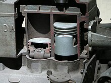
The piston transforms the energy of the expanding gasses into mechanical energy. The piston rides in the cylinder liner or sleeve as shown in Figure 6 and Figure 7.
Pistons are commonly made of aluminum or cast iron alloys. To prevent the combustion gasses from bypassing the piston and to keep friction to a minimum, each piston has several metal rings around it, as illustrated by Figure 10.

These rings function as the seal between the piston and the cylinder wall and also act to reduce friction by minimizing the contact area between the piston and the cylinder wall. The rings are usually made of cast iron and coated with chrome or molybdenum. Most diesel engine pistons have several rings, usually 2 to 5, with each ring performing a distinct function. The top ring(s) acts primarily as the pressure seal. The intermediate ring(s) acts as a wiper ring to remove and control the amount of oil film on the cylinder walls. The bottom ring(s) is an oiler ring and ensures that a supply of lubricating oil is evenly deposited on the cylinder walls.
The connecting rod connects the piston to the crankshaft. See Figure 6 and Figure 7 for the location of the connecting rods in an engine. The rods are made from drop-forged, heat-treated steel to provide the required strength. Each end of the rod is bored, with the smaller top bore connecting to the piston pin (wrist pin) in the piston as shown in Figure 10. The large bore end of the rod is split in half and bolted to allow the rod to be attached to the crankshaft. Some diesel engine connecting rods are drilled down the center to allow oil to travel up from the crankshaft and into the piston pin and piston for lubrication.
A variation found in V-type engines that affects the connecting rods is to position the cylinders in the left and right banks directly opposite each other instead of staggered (most common configuration). This arrangement requires that the connecting rods of two opposing cylinders share the same main journal bearing on the crankshaft. To allow this configuration, one of the connecting rods must be split or forked around the other.
The crankshaft transforms the linear motion of the pistons into a rotational motion that is transmitted to the load. Crankshafts are made of forged steel. The forged crankshaft is machined to produce the crankshaft bearing and connecting rod bearing surfaces. The rod bearings are eccentric, or offset, from the center of the crankshaft as illustrated in Figure 11. This offset converts the reciprocating (up and down) motion of the piston into the rotary motion of the crankshaft. The amount of offset determines the stroke (distance the piston travels) of the engine (discussed later).
The crankshaft does not ride directly on the cast iron block crankshaft supports, but rides on special bearing material as shown in Figure 11. The connecting rods also have bearings inserted between the crankshaft and the connecting rods. The bearing material is a soft alloy of metals that provides a replaceable wear surface and prevents galling between two similar metals (i.e., crankshaft and connecting rod). Each bearing is split into halves to allow assembly of the engine. The crankshaft is drilled with oil passages that allow the engine to feed oil to each of the crankshaft bearings and connection rod bearings and up into the connecting rod itself.
The crankshaft has large weights, called counter weights, that balance the weight of the connecting rods. These weights ensure an even (balance) force during the rotation of the moving parts.

The flywheel is located on one end of the crankshaft and serves three purposes. First, through its inertia, it reduces vibration by smoothing out the power stroke as each cylinder fires. Second, it is the mounting surface used to bolt the engine up to its load. Third, on some diesels, the flywheel has gear teeth around its perimeter that allow the starting motors to engage and crank the diesel.
A diesel engine's cylinder heads perform several functions. First, they provide the top seal for the cylinder bore or sleeve. Second, they provide the structure holding exhaust valves (and intake valves where applicable), the fuel injector, and necessary linkages. A diesel engine's heads are manufactured in one of two ways. In one method, each cylinder has its own head casting, which is bolted to the block. This method is used primarily on the larger diesel engines. In the second method, which is used on smaller engines, the engine's head is cast as one piece (multi-cylinder head).
Diesel engines have two methods of admitting and exhausting gasses from the cylinder.
They can use either ports or valves or a combination of both. Ports are slots in the cylinder walls located in the lower 1/3 of the bore. See Figure 6 and Figure 7 for examples of intake ports, and note their relative location with respect to the rest of the engine. When the piston travels below the level of the ports, the ports are "opened" and fresh air or exhaust gasses are able to enter or leave, depending on the type of port.
The ports are then "closed" when the piston travels back above the level of the ports. Valves (refer to figure 12) are mechanically opened and closed to admit or exhaust the gasses as needed. The valves are located in the head casting of the engine. The point at which the valve seals against the head is called the valve seat. Most medium-sized diesels have either intake ports or exhaust valves or both intake and exhaust valves.

In order for a diesel engine to operate, all of its components must perform their functions at very precise intervals in relation to the motion of the piston.
To accomplish this, a component called a camshaft is used. Figure 13 illustrates a camshaft and camshaft drive gear. Figure 6 and Figure 7 illustrate the location of a camshaft in a large overhead cam diesel engine.
A camshaft is a long bar with egg-shaped eccentric lobes, one lobe for each valve and fuel injector (discussed later). Each lobe has a follower as shown on Figure 14. As the camshaft is rotated, the follower is forced up and down as it follows the profile of the cam lobe. The followers are connected to the engine's valves and fuel injectors through various types of linkages called pushrodsand rocker arms. The pushrods and rocker arms transfer the reciprocating motion generated by the camshaft lobes to the valves and injectors, opening and closing them as needed. The valves are maintained closed by springs.

As the valve is opened by the camshaft, it compresses the valve spring. The energy stored in the valve spring is then used to close the valve as the camshaft lobe rotates out from under the follower. Because an engine experiences fairly large changes in temperature (e.g., ambient to a normal running temperature of about 190°F;), its components must be designed to allow for thermal expansion. Therefore, the valves, valve pushrods, and rocker arms must have some method of allowing for the expansion.
This is accomplished by the use of valve lash. Valve lash is the term given to the "slop" or "give" in the valve train before the cam actually starts to open the valve.
The camshaft is driven by the engine's crankshaft through a series of gears called idler gears and timing gears. The gears allow the rotation of the camshaft to correspond or be in time with, the rotation of the crankshaft and thereby allows the valve opening, valve closing, and injection of fuel to be timed to occur at precise intervals in the piston's travel. To increase the flexibility in timing the valve opening, valve closing, and injection of fuel, and to increase power or to reduce cost, an engine may have one or more camshafts. Typically, in a medium to large V-type engine, each bank will have one or more camshafts per head. In the larger engines, the intake valves, exhaust valves, and fuel injectors may share a common camshaft or have independent camshafts.

Depending on the type and make of the engine, the location of the camshaft or shafts varies. The camshaft(s) in an in-line engine is usually found either in the head of the engine or in the top of the block running down one side of the cylinder bank. Figure 14 provides an example of an engine with the camshaft located on the side of the engine.
Figure 3 provides an example of an overhead cam arrangement as on a V-type engine.
On small or mid-sized V-type engines, the camshaft is usually located in the block at the center of the "V" between the two banks of cylinders. In larger or multi-camshafted V-type engines, the camshafts are usually located in the heads.
The diesel engine's blower is part of the air intake system and serves to compress the incoming fresh air for delivery to the cylinders for combustion. The location of the blower is shown on Figure 6. The blower can be part of either a turbocharged or supercharged air intake system. Additional information on these two types of blowers is provided later in this module.
A diesel engine requires five supporting systems in order to operate: cooling, lubrication, fuel injection, air intake, and exhaust. Depending on the size, power, and application of the diesel, these systems vary in size and complexity.
Nearly all diesel engines rely on a liquid cooling system to transfer waste heat out of the block and internals as shown in Figure 15. The cooling system consists of a closed loop similar to that of a car engine and contains the following major components: water pump, radiator or heat exchanger, water jacket (which consists of coolant passages in the block and heads), and a thermostat.

An internal combustion engine would not run for even a few minutes if the moving parts were allowed to make metal-to-metal contact. The heat generated due to the tremendous amounts of friction would melt the metals, leading to the destruction of the engine. To prevent this, all moving parts ride on a thin film of oil that is pumped between all the moving parts of the engine.
Once between the moving parts, the oil serves two purposes. One purpose is to lubricate the bearing surfaces. The other purpose is to cool the bearings by absorbing the friction generated heat. The flow of oil to the moving parts is accomplished by the engine's internal lubricating system.

Oil is accumulated and stored in the engine's oil pan where one or more oil pumps take a suction and pump the oil through one or more oil filters as shown in Figure 16. The filters clean the oil and remove any metal that the oil has picked up due to wear. The cleaned oil then flows up into the engine's oil galleries. A pressure relief valve(s) maintains oil pressure in the galleries and returns oil to the oil pan upon high pressure.
The oil galleries distribute the oil to all the bearing surfaces in the engine.
Once the oil has cooled and lubricated the bearing surfaces, it flows out of the bearing and gravity-flows back into the oil pan. In medium to large diesel engines, the oil is also cooled before being distributed into the block. This is accomplished by either an internal or external oil cooler. The lubrication system also supplies oil to the engine's governor, which is discussed later in this module.
All diesel engines require a method to store and deliver fuel to the engine. Because diesel engines rely on injectors which are precision components with extremely tight tolerances and very small injection hole(s), the fuel delivered to the engine must be extremely clean and free of contaminants.
The fuel system must, therefore, not only deliver the fuel but also ensure its cleanliness. This is usually accomplished through a series of in-line filters.
Commonly, the fuel will be filtered once outside the engine and then the fuel will pass through at least one more filter internal to the engine, usually located in the fuel line at each fuel injector.

In a diesel engine, the fuel system is much more complex than the fuel system on a simple gasoline engine because the fuel serves two purposes. One purpose is obviously to supply the fuel to run the engine; the other is to act as a coolant to the injectors. To meet this second purpose, diesel fuel is kept continuously flowing through the engine's fuel system at a flow rate much higher than required to simply run the engine, an example of a fuel flowpath is shown in Figure 17. The excess fuel is routed back to the fuel pump or the fuel storage tank depending on the application.
Because a diesel engine requires close tolerances to achieve its compression ratio, and because most diesel engines are either turbocharged or supercharged, the air entering the engine must be clean, free of debris, and as cool as possible. Turbocharging and supercharging are discussed in more detail later in this chapter. Also, to improve a turbocharged or supercharged engine's efficiency, the compressed air must be cooled after being compressed. The air intake system is designed to perform these tasks.
Air intake systems vary greatly from vendor to vendor but are usually one of two types, wet or dry. In a wet filter intake system, as shown in Figure 18, the air is sucked or bubbled through a housing that holds a bath of oil such that the dirt in the air is removed by the oil in the filter. The air then flows through a screen-type material to ensure any entrained oil is removed from the air. In a dry filter system, paper, cloth, or a metal screen material is used to catch and trap dirt before it enters the engine (similar to the type used in automobile engines).

In addition to cleaning the air, the intake system is usually designed to intake fresh air from as far away from the engine as practicable, usually just outsid

A piston is a component of reciprocating engines, reciprocating pumps, gas compressors and pneumatic cylinders, among other similar mechanisms. It is the moving component that is contained by a cylinder and is made gas-tight by piston rings. In an engine, its purpose is to transfer force from expanding gas in the cylinder to the crankshaft via a piston rod and/or connecting rod. In a pump, the function is reversed and force is transferred from the crankshaft to the piston for the purpose of compressing or ejecting the fluid in the cylinder. In some engines, the piston also acts as a valve by covering and uncovering ports in the cylinder wall.

An internal combustion engine is acted upon by the pressure of the expanding combustion gases in the combustion chamber space at the top of the cylinder. This force then acts downwards through the connecting rod and onto the crankshaft. The connecting rod is attached to the piston by a swivelling gudgeon pin (US: wrist pin). This pin is mounted within the piston: unlike the steam engine, there is no piston rod or crosshead (except big two stroke engines).
The pin itself is of hardened steel and is fixed in the piston, but free to move in the connecting rod. A few designs use a 'fully floating' design that is loose in both components. All pins must be prevented from moving sideways and the ends of the pin digging into the cylinder wall, usually bycirclips.
Gas sealing is achieved by the use of piston rings. These are a number of narrow iron rings, fitted loosely into grooves in the piston, just below the crown. The rings are split at a point in the rim, allowing them to press against the cylinder with a light spring pressure. Two types of ring are used: the upper rings have solid faces and provide gas sealing; lower rings have narrow edges and a U-shaped profile, to act as oil scrapers. There are many proprietary and detail design features associated with piston rings.
Pistons are cast from aluminium alloys. For better strength and fatigue life, some racing pistons may be forged instead. Early pistons were of cast iron, but there were obvious benefits for engine balancing if a lighter alloy could be used. To produce pistons that could survive engine combustion temperatures, it was necessary to develop new alloys such as Y alloy and Hiduminium, specifically for use as pistons.
A few early gas
engines had double-acting
cylinders, but otherwise effectively all internal combustion
engine pistons are single-acting.
During World War II,
the US submarine Pompano was fitted with
a prototype of the infamously unreliable H.O.R. double-acting two-stroke
diesel engine. Although compact, for use in a cramped submarine,
this design of engine was not repeated. ![]() Media related
to Internal combustion
engine pistons at Wikimedia Commons
Media related
to Internal combustion
engine pistons at Wikimedia Commons
Trunk pistons are long, relative to their diameter. They act both as a piston and as a cylindrical crosshead. As the connecting rod is angled for part of its rotation, there is also a side force that reacts along the side of the piston against the cylinder wall. A longer piston helps to support this.
Trunk pistons have been a common design of piston since the early days of the reciprocating internal combustion engine. They were used for both petrol and diesel engines, although high speed engines have now adopted the lighter weight slipper piston.
A characteristic of most trunk pistons, particularly for diesel engines, is that they have a groove for an oil ring below the gudgeon pin, not just the rings between the gudgeon pin and crown.
The name 'trunk piston' derives from the 'trunk engine', an early design of marine steam engine. To make these more compact, they avoided the steam engine's usual piston rodand separate crosshead and were instead the first engine design to place the gudgeon pin directly within the piston. Otherwise these trunk engine pistons bore little resemblance to the trunk piston: they were of extremely large diameter and were double-acting. Their 'trunk' was a narrow cylinder placed mounted in the centre of this piston.
![]() Media related
to Trunk
pistons at Wikimedia Commons
Media related
to Trunk
pistons at Wikimedia Commons
Large slow-speed Diesel engines may require additional support for the side forces on the piston. These engines typically use crosshead pistons. The main piston has a largepiston rod extending downwards from the piston to what is effectively a second smaller-diameter piston. The main piston is responsible for gas sealing and carries the piston rings. The smaller piston is purely a mechanical guide. It runs within a small cylinder as a trunk guide and also carries the gudgeon pin.
Because of the additional weight of these pistons, they are not used for high-speed engines.
![]() Media related
to Crosshead
pistons at Wikimedia Commons
Media related
to Crosshead
pistons at Wikimedia Commons

A slipper piston is a piston for a petrol engine that has been reduced in size and weight as much as possible. In the extreme case, they are reduced to the piston crown, support for the piston rings, and just enough of the piston skirt remaining to leave two lands so as to stop the piston rocking in the bore. The sides of the piston skirt around the gudgeon pin are reduced away from the cylinder wall. The purpose is mostly to reduce the reciprocating mass, thus making it easier to balance the engine and so permit high speeds. A secondary benefit may be some reduction in friction with the cylinder wall, however as most of this is due to the parts of the piston that are left behind, the benefit is minor.
![]() Media related
to Slipper
pistons at Wikimedia Commons
Media related
to Slipper
pistons at Wikimedia Commons

Deflector pistons are used in two-stroke engines with crankcase compression, where the gas flow within the cylinder must be carefully directed in order to provide efficient scavenging. With cross scavenging, the transfer (inlet to the cylinder) and exhaust ports are on directly facing sides of the cylinder wall. To prevent the incoming mixture passing straight across from one port to the other, the piston has a raised rib on its crown. This is intended to deflect the incoming mixture upwards, around the combustion chamber. Much effort, and many different designs of piston crown, went into developing improved scavenging. The crowns developed from a simple rib to a large asymmetric bulge, usually with a steep face on the inlet side and a gentle curve on the exhaust. Despite this, cross scavenging was never as effective as hoped. Most engines today use Schnuerle porting instead. This places a pair of transfer ports in the sides of the cylinder and encourages gas flow to rotate around a vertical axis, rather than a horizontal axis.
![]() Media related
to Deflector
pistons at Wikimedia Commons
Media related
to Deflector
pistons at Wikimedia Commons

Steam engines are usually double-acting (i.e. steam pressure acts alternately on each side of the piston) and the admission and release of steam is controlled by slide valves, piston valves or poppet valves. Consequently, steam engine pistons are nearly always comparatively thin discs: their diameter is several times their thickness. (One exception is the trunk engine piston, shaped more like those in a modern internal-combustion engine.)

Internal combustion engines can contain any number of combustion chambers (cylinders), with numbers between one and twelve being common, though as many as 36 (Lycoming R-7755) have been used. Having more cylinders in an engine yields two potential benefits: first, the engine can have a larger displacement with smaller individual reciprocating masses, that is, the mass of each piston can be less thus making a smoother-running engine since the engine tends to vibrate as a result of the pistons moving up and down. Doubling the number of the same size cylinders will double the torque and power. The downside to having more pistons is that the engine will tend to weigh more and generate more internal friction as the greater number of pistons rub against the inside of their cylinders. This tends to decrease fuel efficiency and robs the engine of some of its power. For high-performance gasoline engines using current materials and technology, such as the engines found in modern automobiles, there seems to be a point around 10 or 12 cylinders after which the addition of cylinders becomes an overall detriment to performance and efficiency. Although, exceptions such as the W16 engine from Volkswagenexist.
The ignition system of an internal combustion engines depends on the type of engine and the fuel used. Petrol engines are typically ignited by a precisely timed spark, and diesel engines by compression heating. Historically, outside flame and hot-tube systems were used, see hot bulb engine.
The mixture is ignited by an electric spark from a spark plug — the timing of which is very precisely controlled. Almost all gasoline engines are of this type. Diesel engines timing is precisely controlled by the pressure pump and injector.
Ignition occurs as the temperature of the fuel/air mixture is taken over its autoignition temperature, due to heat generated by the compression of the air during the compression stroke. The vast majority of compression ignition engines are diesels in which the fuel is mixed with the air after the air has reached ignition temperature. In this case, the timing comes from the fuel injection system. Very small model engines for which simplicity and light weight is more important than fuel costs use easily ignited fuels (a mixture of kerosene, ether, and lubricant) and adjustable compression to control ignition timing for starting and running.
For reciprocating engines, the point in the cycle at which the fuel-oxidizer mixture is ignited has a direct effect on the efficiency and output of the ICE. The thermodynamics of the idealized Carnot heat engine tells us that an ICE is most efficient if most of the burning takes place at a high temperature, resulting from compression — near top dead center. The speed of the flame front is directly affected by the compression ratio, fuel mixture temperature, and octane rating or cetane number of the fuel. Leaner mixtures and lower mixture pressures burn more slowly requiring more advanced ignition timing. It is important to have combustion spread by a thermal flame front (deflagration), not by a shock wave. Combustion propagation by a shock wave is called detonation and, in engines, is also known as pinging or Engine knocking.
So at least in gasoline-burning engines, ignition timing is largely a compromise between a later "retarded" spark — which gives greater efficiency with high octane fuel — and an earlier "advanced" spark that avoids detonation with the fuel used. For this reason, high-performance diesel automobile proponents, such as Gale Banks, believe that
There’s only so far you can go with an air-throttled engine on 91-octane gasoline. In other words, it is the fuel, gasoline, that has become the limiting factor. ... While turbocharging has been applied to both gasoline and diesel engines, only limited boost can be added to a gasoline engine before the fuel octane level again becomes a problem. With a diesel, boost pressure is essentially unlimited. It is literally possible to run as much boost as the engine will physically stand before breaking apart. Consequently, engine designers have come to realize that diesels are capable of substantially more power and torque than any comparably sized gasoline engine.

Fuels burn faster and more efficiently when they present a large surface area to the oxygen in air. Liquid fuels must be atomized to create a fuel-air mixture, traditionally this was done with a carburetor in petrol engines and with fuel injection in diesel engines. Most modern petrol engines now use fuel injection too — though the technology is quite different. While diesel must be injected at an exact point in that engine cycle, no such precision is needed in a petrol engine. However, the lack of lubricity in petrol means that the injectors themselves must be more sophisticated.
Simpler reciprocating engines continue to use a carburetor to supply fuel into the cylinder. Although carburetor technology in automobiles reached a very high degree of sophistication and precision, from the mid-1980s it lost out on cost and flexibility to fuel injection. Simple forms of carburetor remain in widespread use in small engines such as lawn mowers and more sophisticated forms are still used in small motorcycles.
Larger gasoline engines used in automobiles have mostly moved to fuel injection systems (see Gasoline Direct Injection). Diesel engines have always used fuel injection system because the timing of the injection initiates and controls the combustion.
Autogas engines use either fuel injection systems or open- or closed-loop carburetors.
Most internal combustion engines now require a fuel pump. Diesel engines use an all-mechanical precision pump system that delivers a timed injection direct into the combustion chamber, hence requiring a high delivery pressure to overcome the pressure of the combustion chamber. Petrol fuel injection delivers into the inlet tract at atmospheric pressure (or below) and timing is not involved, these pumps are normally driven electrically. Gas turbine and rocket engines use electrical systems.
Other internal combustion engines like jet engines and rocket engines employ various methods of fuel delivery including impinging jets, gas/liquid shear, preburners and others.
Some engines such as solid rockets have oxidisers already within the combustion chamber but in most cases for combustion to occur, a continuous supply of oxidiser must be supplied to the combustion chamber.
When air is used with piston engines it can simply suck it in as the piston increases the volume of the chamber. However, this gives a maximum of 1 atmosphere of pressure difference across the inlet valves, and at high engine speeds the resulting airflow can limit potential output
A supercharger is a "forced induction" system which uses a compressor powered by the shaft of the engine which forces air through the valves of the engine to achieve higher flow. When these systems are employed the maximum absolute pressure at the inlet valve is typically around 2 times atmospheric pressure or more.

Turbochargers are another type of forced induction system which has its compressor powered by a gas turbine running off the exhaust gases from the engine.
Turbochargers and superchargers are particularly useful at high altitudes and they are frequently used in aircraft engines.
Duct jet engines use the same basic system, but eschew the piston engine, and replace it with a burner instead.
In liquid rocket engines, the oxidiser comes in the form of a liquid and needs to be delivered at high pressure (typically 10-230 bar or 1–23 MPa) to the combustion chamber. This is normally achieved by the use of a centrifugal pump powered by a gas turbine — a configuration known as a turbopump, but it can also be pressure fed.

For a four-stroke engine, key parts of the engine include the crankshaft (purple), connecting rod (orange), one or more camshafts (red and blue), and valves. For a two-stroke engine, there may simply be an exhaust outlet and fuel inlet instead of a valve system. In both types of engines there are one or more cylinders (grey and green), and for each cylinder there is aspark plug (darker-grey, gasoline engines only), a piston (yellow), and a crankpin (purple). A single sweep of the cylinder by the piston in an upward or downward motion is known as a stroke. The downward stroke that occurs directly after the air-fuel mix passes from thecarburetor or fuel injector to the cylinder (where it is ignited) is also known as a power stroke.
A Wankel engine has a triangular rotor that orbits in an epitrochoidal (figure 8 shape) chamber around an eccentric shaft. The four phases of operation (intake, compression, power, and exhaust) take place in what is effectively a moving, variable-volume chamber.
All four-stroke internal combustion engines employ valves to control the admittance of fuel and air into the combustion chamber. Two-stroke engines use ports in the cylinder bore, covered and uncovered by the piston, though there have been variations such as exhaust valves.
In piston engines, the valves are grouped into 'inlet valves' which admit the entrance of fuel and air and 'outlet valves' which allow the exhaust gases to escape. Each valve opens once per cycle and the ones that are subject to extreme accelerations are held closed by springs that are typically opened by rods running on a camshaft rotating with the engines' crankshaft.
Continuous combustion engines—as well as piston engines—usually have valves that open and close to admit the fuel and/or air at the startup and shutdown. Some valves feather to adjust the flow to control power or engine speed as well.

Internal combustion engines have to effectively manage the exhaust of the cooled combustion gas from the engine. The exhaust system frequently contains devices to control pollution, both chemical and noise pollution. In addition, for cyclic combustion engines the exhaust system is frequently tuned to improve emptying of the combustion chamber. The majority of exhausts also have systems to prevent heat from reaching places which would encounter damage from it such as heat-sensitive components, often referred to as Exhaust Heat Management.
For jet propulsion internal combustion engines, the 'exhaust system' takes the form of a high velocity nozzle, which generates thrust for the engine and forms a colimated jet of gas that gives the engine its name.
Combustion generates a great deal of heat, and some of this transfers to the walls of the engine. Failure will occur if the body of the engine is allowed to reach too high a temperature; either the engine will physically fail, or any lubricants used will degrade to the point that they no longer protect the engine. The lubricants must be clean as dirty lubricants may lead to over formation of sludge in the engines.
Cooling systems usually employ air (air-cooled) or liquid (usually water) cooling, while some very hot engines using radiative cooling (especially some rocket engines). Some high-altitude rocket engines use ablative cooling, where the walls gradually erode in a controlled fashion. Rockets in particular can use regenerative cooling, which uses the fuel to cool the solid parts of the engine.
A piston is a component of reciprocating engines. It is located in a cylinder and is made gas-tight by piston rings. Its purpose is to transfer force from expanding gas in the cylinder to the crankshaft via a piston rod and/or connecting rod. In two-stroke engines the piston also acts as a valve by covering and uncovering ports in the cylinder wall.
For jet engine forms of internal combustion engines, a propelling nozzle is present. This takes the high temperature, high pressure exhaust and expands and cools it. The exhaust leaves the nozzle going at much higher speed and provides thrust, as well as constricting the flow from the engine and raising the pressure in the rest of the engine, giving greater thrust for the exhaust mass that exits.

Most reciprocating internal combustion engines end up turning a shaft. This means that the linear motion of a piston must be converted into rotation. This is typically achieved by a crankshaft.
The flywheel is a disk or wheel attached to the crank, forming an inertial mass that stores rotational energy. In engines with only a single cylinder the flywheel is essential to carry energy over from the power stroke into a subsequent compression stroke. Flywheels are present in most reciprocating engines to smooth out the power delivery over each rotation of the crank and in most automotive engines also mount a gear ring for a starter. The rotational inertia of the flywheel also allows a much slower minimum unloaded speed and also improves the smoothness at idle. The flywheel may also perform a part of the balancing of the system and so by itself be out of balance, although most engines will use a neutral balance for the flywheel, enabling it to be balanced in a separate operation. The flywheel is also used as a mounting for the clutch or a torque converter in most automotive applications.
All internal combustion engines require some form of system to get them into operation. Most piston engines use a starter motor powered by the same battery as runs the rest of the electric systems. Large jet engines and gas turbines are started with a compressed air motor that is geared to one of the engine's driveshafts. Compressed air can be supplied from another engine, a unit on the ground or by the aircraft's APU. Small internal combustion engines are often started by pull cords. Motorcycles of all sizes were traditionally kick-started, though all but the smallest are now electric-start. Large stationary and marine engines may be started by the timed injection of compressed air into the cylinders — or occasionally with cartridges. Jump starting refers to assistance from another battery (typically when the fitted battery is discharged), while bump starting refers to an alternative method of starting by the application of some external force, e.g. rolling down a hill.
These systems often work in combination with engine cooling and exhaust systems. Heat shielding is necessary to prevent engine heat from damaging heat-sensitive components. The majority of older cars use simple steel heat shielding to reduce thermal radiation and convection. It is now most common for modern cars are to use aluminium heat shielding which has a lower density, can be easily formed and does not corrode in the same way as steel. Higher performance vehicles are beginning to use ceramic heat shielding as this can withstand far higher temperatures as well as further reductions in heat transfer.
Internal combustions engines require lubrication in operation that moving parts slide smoothly over each other. Insufficient lubrication subjects the parts of the engine to metal-to-metal contact, friction, heat build-up, rapid wear often culminating in parts becoming friction welded together e.g. pistons in their cylinders. Big end bearings seizing up will sometimes lead to a connecting rod breaking and poking out through the crankcase.
Several different types of lubrication systems are used. Simple two-stroke engines are lubricated by oil mixed into the fuel or injected into the induction stream as a spray. Early slow-speed stationary and marine engines were lubricated by gravity from small chambers similar to those used on steam engines at the time — with an engine tender refilling these as needed. As engines were adapted for automotive and aircraft use, the need for a high power-to-weight ratio led to increased speeds, higher temperatures, and greater pressure on bearings which in turn required pressure-lubrication for crank bearings and connecting-rod journals. This was provided either by a direct lubrication from a pump, or indirectly by a jet of oil directed at pickup cups on the connecting rod ends which had the advantage of providing higher pressures as the engine speed increased.
Most engines require one or more systems to start and shut down the engine and to control parameters such as the power, speed, torque, pollution, combustion temperature, and efficiency and to stabilise the engine from modes of operation that may induce self-damage such as pre-ignition. Such systems may be referred to as engine control units.
Many control systems today are digital, and are frequently termed FADEC (Full Authority Digital Electronic Control) systems.
Engine On Board Diagnostics (also known as OBD) is a computerized system that allows for electronic diagnosis of a vehicles' powerplant. The first generation, known as OBD1, was introduced 10 years after the U.S. Congress passed the Clean Air Act in 1970 as a way to monitor a vehicles' fuel injection system. OBD2, the second generation of computerized on-board diagnostics, was codified and recommended by the California Air Resource Board in 1994 and became mandatory equipment aboard all vehicles sold in the United States as of 1996.
An ignition system is a system for igniting a fuel-air mixture. Ignition systems are well known in the field of internal combustion engines such as those used in petrol (gasoline) engines used to power the majority of motor vehicles, but they are also used in many other applications such as in oil-fired and gas-fired boilers, rocket engines, etc.
The first ignition system to use an electric spark was probably Alessandro Volta's toy electric pistol from the 1780s. Virtually all petrol engines today use an electric spark for ignition.
Diesel engines rely on fuel compression for ignition, but usually also have glowplugs that preheat the combustion chamber to allow starting of the engine in cold weather. Other engines may use a flame, or a heated tube, for ignition.

The simplest form of spark ignition is that using a magneto. The engine spins a magnet inside a coil, or, in the earlier designs, a coil inside a fixed magnet, and also operates a contact breaker, interrupting the current and causing the voltage to be increased sufficiently to jump a small gap. The spark plugs are connected directly from the magneto output. Early magnetos had one coil, with the contact breaker (sparking plug) inside the combustion chamber. In about 1902, Bosch introduced a double-coil magneto, with a fixed sparking plug, and the contact breaker outside the cylinder. Magnetos are not used in modern cars, but because they generate their own electricity they are often found on piston-engined aircraft engines and small engines such as those found in mopeds, lawnmowers, snowblowers, chainsaws, etc. where a battery-based electrical system is not present for any combination of necessity, weight, cost, and reliability reasons.
Magnetos were used on the small engine's ancestor, the stationary "hit and miss" engine which was used in the early twentieth century, on older gasoline or distillate farm tractors before battery starting and lighting became common, and on aircraft piston engines. Magnetos were used in these engines because their simplicity and self-contained operation was more reliable, and because magnetos weighed less than having a battery and dynamo or alternator.
Aircraft engines usually have dual magnetos to provide redundancy in the event of a failure, and to increase efficiency by thoroughly and quickly burning the fuel air mix from both sides towards the center. The Wright brothers used a magneto invented in 1902 and built for them in 1903 by Dayton, Ohio inventor, Vincent Groby Apple.[1] Some older automobiles had both a magneto system and a battery actuated system (see below) running simultaneously to ensure proper ignition under all conditions with the limited performance each system provided at the time. This gave the benefits of easy starting (from the battery system) with reliable sparking at speed (from the magneto).

The output of a magneto depends on the speed of the engine, and therefore starting can be problematic. Some magnetos include an impulse system, which spins the magnet quickly at the proper moment, making easier starting at slow cranking speeds. Some engines, such as aircraft but also the Ford Model T, used a system which relied on non rechargeable dry cells, (similar to a large flashlight battery, and which was not maintained by a charging system as on modern automobiles) to start the engine or for starting and running at low speed. The operator would manually switch the ignition over to magneto operation for high speed operation.
To provide high voltage for the spark from the low voltage batteries, a 'tickler' was used, which was essentially a larger version of the once widespread electric buzzer. With this apparatus, the direct current passes through an electromagnetic coil which pulls open a pair of contact points, interrupting the current; the magnetic field collapses, the spring-loaded points close again, the circuit is reestablished, and the cycle repeats rapidly. The rapidly collapsing magnetic field, however, induces a high voltage across the coil which can only relieve itself by arcing across the contact points; while in the case of the buzzer this is a problem as it causes the points to oxidize and/or weldtogether, in the case of the ignition system this becomes the source of the high voltage to operate the spark plugs.
In this mode of operation, the coil would "buzz" continuously, producing a constant train of sparks. The entire apparatus was known as the 'Model T spark coil' (in contrast to the modern ignition coil which is only the actual coil component of the system). Long after the demise of the Model T as transportation they remained a popular self-contained source of high voltage for electrical home experimenters, appearing in articles in magazines such as Popular Mechanics and projects for school science fairs as late as the early 1960s. In the UK these devices were commonly known as trembler coils and were popular in cars pre-1910, and also in commercial vehicles with large engines until around 1925 to ease starting.
The Model T (built into the flywheel) differed from modern implementations by not providing high voltage directly at the output; the maximum voltage produced was about 30 volts, and therefore also had to be run through the spark coil to provide high enough voltage for ignition, as described above, although the coil would not "buzz" continuously in this case, only going through one cycle per spark. In either case, the low voltage was switched to the appropriate spark plug by the 'timer' mounted on the front of the engine. This performed the equivalent function to the modern distributor, although by directing the low voltage, not the high voltage as for the distributor. The timing of the spark was adjustable by rotating this mechanism through a lever mounted on the steering column. As the precise timing of the spark depends on both the 'timer' and the trembler contacts within the coil, this is less consistent than the breaker points of the later distributor. However for the low speed and the low compression of such early engines, this imprecise timing was acceptable.
With the universal adoption of electrical starting for automobiles, and the availability of a large battery to provide a constant source of electricity, magneto systems were abandoned for systems which interrupted current at battery voltage, used an ignition coil (a transformer) to step the voltage up to the needs of the ignition, and a distributor to route the ensuing pulse to the correct spark plug at the correct time.
The first reliable battery operated ignition was developed by the Dayton Engineering Laboratories Co. (Delco) and introduced in the 1910 Cadillac. This ignition was developed byCharles Kettering and was a wonder in its day. It consisted of a single coil, points (the switch), a capacitor and a distributor set up to allocate the spark from the ignition coil timed to the correct cylinder. The coil was basically a transformer to step up the low battery voltage (6 or 12 V) to the high ignition voltage required to jump a spark plug gap.
The points allow the coil magnetic field to build and then, when the points are opened by a cam arrangement, the magnetic field collapses and a large voltage (20 kV or greater) is produced. The capacitor has two functions: 1) it absorbs the back EMF from the magnetic field in the coil to minimize point contact burning and maximize point life; and 2) it forms a resonant circuit with the ignition coil transferring further energy to the secondary side until the energy is exhausted.[2] The Kettering system became the primary ignition system for many years in the automotive industry due to its lower cost, higher reliability and relative simplicity.
The ignition system is typically controlled by a key operated Ignition switch.

Most four-stroke engines have used a mechanically timed electrical ignition system. The heart of the system is the distributor. The distributor contains a rotating cam driven by the engine's drive, a set of breaker points, a condenser, a rotor and a distributor cap. External to the distributor is the ignition coil, the spark plugs and wires linking the distributor to the spark plugs and ignition coil. (see diagram Below)
The system is powered by a lead-acid battery, which is charged by the car's electrical system using a dynamo or alternator. The engine operates contact breaker points, which interrupt the current to an induction coil (known as the ignition coil).
The ignition coil consists of two transformer windings sharing a common magnetic core—the primary and secondary windings. An alternating current in the primary induces alternating magnetic field in the coil's core. Because the ignition coil's secondary has far more windings than the primary, the coil is a step-up transformer which induces a much higher voltage across the secondary windings. For an ignition coil, one end of windings of both the primary and secondary are connected together. This common point is connected to the battery (usually through a current-limiting ballast resistor). The other end of the primary is connected to the points within the contact breaker. The other end of the secondary is connected, via the distributor cap and rotor, to the spark plugs.

The ignition firing sequence begins with the points (or contact breaker) closed. A steady current flows from the battery, through the current-limiting resistor, through the coil primary, across the closed breaker points and finally back to the battery. This current produces a magnetic field within the coil's core. This magnetic field forms the energy reservoir that will be used to drive the ignition spark.
As the engine turns, so does the cam inside the distributor. The points ride on the cam so that as the engine turns and reaches the top of the engine's compression cycle, a high point in the cam causes the breaker points to open. This breaks the primary winding's circuit and abruptly stops the current through the breaker points. Without the steady current through the points, the magnetic field generated in the coil immediately and rapidly collapses. This change in the magnetic field induces a high voltage in the coil's secondary windings.
At the same time, current exits the coil's primary winding and begins to charge up the capacitor (condenser) that lies across the now-open breaker points. This capacitor and the coil’s primary windings form an oscillating LC circuit. This LC circuit produces a damped, oscillating current which bounces energy between the capacitor’s electric field and the ignition coil’s magnetic field. The oscillating current in the coil’s primary, which produces an oscillating magnetic field in the coil, extends the high voltage pulse at the output of the secondary windings. This high voltage thus continues beyond the time of the initial field collapse pulse. The oscillation continues until the circuit’s energy is consumed.
The ignition coil's secondary windings are connected to the distributor cap. A turning rotor, located on top of the breaker cam within the distributor cap, sequentially connects the coil's secondary windings to one of the several wires leading to each cylinder's spark plug. The extremely high voltage from the coil's secondary (typically 20,000 to 50,000 volts) causes a spark to form across the gap of the spark plug. This, in turn, ignites the compressed air-fuel mixture within the engine. It is the creation of this spark which consumes the energy that was stored in the ignition coil’s magnetic field.
The flat twin cylinder 1948 Citroën 2CV used one double ended coil without a distributor, and just contact breakers, in a wasted spark system.

Some two-cylinder motorcycles and motor scooters had two contact points feeding twin coils each connected directly to the spark plug without a distributor; e.g. the BSA Thunderbolt and Triumph Tigress.
High performance engines with eight or more cylinders that operate at high r.p.m. (such as those used in motor racing) demand both a higher rate of spark and a higher spark energy than the simple ignition circuit can provide. This problem is overcome by using either of these adaptations:
A distributor-based system is not greatly different from a magneto system except that more separate elements are involved. There are also advantages to this arrangement. For example, the position of the contact breaker points relative to the engine angle can be changed a small amount dynamically, allowing the ignition timing to be automatically advanced with increasing revolutions per minute (RPM) or increased manifold vacuum, giving better efficiency and performance.
However it is necessary to check periodically the maximum opening gap of the breaker(s), using a feeler gauge, since this mechanical adjustment affects the "dwell" time during which the coil charges, and breakers should be re-dressed or replaced when they have become pitted by electric arcing. This system was used almost universally until the late 1970s, when electronic ignition systems started to appear.
The disadvantage of the mechanical system is the use of breaker points to interrupt the low-voltage high-current through the primary winding of the coil; the points are subject to mechanical wear where they ride the cam to open and shut, as well as oxidation and burning at the contact surfaces from the constant sparking. They require regular adjustment to compensate for wear, and the opening of the contact breakers, which is responsible for spark timing, is subject to mechanical variations.
In addition, the spark voltage is also dependent on contact effectiveness, and poor sparking can lead to lower engine efficiency. A mechanical contact breaker system cannot control an average ignition current of more than about 3 A while still giving a reasonable service life, and this may limit the power of the spark and ultimate engine speed.

Electronic ignition (EI) solves these problems. In the initial systems, points were still used but they handled only a low current which was used to control the high primary current through a solid state switching system. Soon, however, even these contact breaker points were replaced by an angular sensor of some kind - either optical, where a vaned rotor breaks a light beam, or more commonly using a Hall effect sensor, which responds to a rotating magnet mounted on the distributor shaft. The sensor output is shaped and processed by suitable circuitry, then used to trigger a switching device such as a thyristor, which switches a large current through the coil.
The first electronic ignition (a cold cathode type) was tested in 1948 by Delco-Remy, while Lucas introduced a transistorized ignition in 1955, which was used on BRM andCoventry Climax Formula One engines in 1962. The aftermarket began offering EI that year, with both the AutoLite Electric Transistor 201 and Tung-Sol EI-4 (thyratron capacitive discharge) being available. Pontiac became the first automaker to offer an optional EI, the breakerless magnetic pulse-triggered Delcotronic, on some 1963 models; it was also available on some Corvettes. The first commercially available all solid-state (SCR) capacitive discharge ignition was manufactured by Hyland Electronics in Canada also in 1963. Ford fitted a Lucas system on the Lotus 25s entered at Indianapolis the next year, ran a fleet test in 1964, and began offering optional EI on some models in 1965. Beginning in 1958, Earl W. Meyer at Chrysler worked on EI, continuing until 1961 and resulting in use of EI on the company's NASCAR hemis in 1963 and 1964.
Prest-O-Lite's CD-65, which relied on capacitance discharge (CD), appeared in 1965, and had "an unprecedented 50,000 mile warranty."(This differs from the non-CD Prest-O-Lite system introduced on AMC products in 1972, and made standard equipment for the 1975 model year.) A similar CD unit was available from Delco in 1966, which was optional on Oldsmobile, Pontiac, and GMC vehicles in the 1967 model year. Also in 1967, Motorola debuted their breakerless CD system. The most famous aftermarket electronic ignition which debuted in 1965, was the Delta Mark 10 capacitive discharge ignition, which was sold assembled or as a kit.
FIAT became the first company to offer standard EI, in 1968, followed by Chrysler (after a 1971 trial) in 1973 and by Ford and GM in 1975.
In 1967, Prest-O-Lite made a "Black Box" ignition amplifier, intended to take the load off of the distributor's breaker points during high r.p.m. runs, which was used by Dodge andPlymouth on their factory Super Stock Coronet and Belvedere drag racers. This amplifier was installed on the interior side of the cars' firewall, and had a duct which provided outside air to cool the unit.[citation needed] The rest of the system (distributor and spark plugs) remains as for the mechanical system. The lack of moving parts compared with the mechanical system leads to greater reliability and longer service intervals.
Chrysler introduced breakerless ignition in mid-1971 as an option for its 340 V8 and the 426 Street Hemi. For the 1972 model year, the system became standard on its high-performance engines (the 340 cu in (5.6 l) and the four-barrel carburetor-equipped 400 hp (298 kW) 400 cu in (7 l)) and was an option on its 318 cu in (5.2 l), 360 cu in (5.9 l), two-barrel 400 cu in (6.6 l), and low-performance 440 cu in (7.2 l) . Breakerless Ignition was standardised across the model range for 1973.
For older cars, it is usually possible to retrofit an EI system in place of the mechanical one. In some cases, a modern distributor will fit into the older engine with no other modifications, like the H.E.I. distributor made by General Motors, the Hot-Spark electronic ignition conversion kit and the aforementioned Chrysler-built electronic ignition system.

Other innovations are currently available on various cars. In some models, rather than one central coil, there are individual coils on each spark plug, sometimes known as direct ignition or coil on plug (COP). This allows the coil a longer time to accumulate a charge between sparks, and therefore a higher energy spark. A variation on this has each coil handle two plugs, on cylinders which are 360 degrees out of phase (and therefore reach TDC at the same time); in the four-cycle engine this means that one plug will be sparking during the end of the exhaust stroke while the other fires at the usual time, a so-called "wasted spark" arrangement which has no drawbacks apart from faster spark plug erosion; the paired cylinders are 1/4 and 2/3. Other systems do away with the distributor as a timing apparatus and use a magnetic crank angle sensor mounted on the crankshaft to trigger the ignition at the proper time.
At the turn of the 21st century digital electronic ignition modules became available for small engines on such applications as chainsaws,string trimmers, leaf blowers, and lawn mowers. This was made possible by low cost, high speed, and small footprint microcontrollers. Digital electronic ignition modules can be designed as either capacitor discharge ignition (CDI) or inductive discharge ignition (IDI) systems. Capacitive discharge digital ignitions store charged energy for the spark in a capacitor within the module that can be released to the spark plug at virtually any time throughout the engine cycle via a control signal from the microprocessor. This allows for greater timing flexibility, and engine performance; especially when designed hand-in-hand with the engine carburetor.
In an Engine Management System (EMS), electronics control fuel delivery and ignition timing. Primary sensors on the system are crankshaft angle (crankshaft or Top Dead Center (TDC) position), airflow into the engine and throttle position. The circuitry determines which cylinder needs fuel and how much, opens the requisite injector to deliver it, then causes a spark at the right moment to burn it. Early EMS systems used an analogue computer to accomplish this, but as embedded systems dropped in price and became fast enough to keep up with the changing inputs at high revolutions, digital systems started to appear.
Some designs using an EMS retain the original ignition coil, distributor and high-tension leads found on cars throughout history. Other systems dispense with the distributor altogether and have individual coils mounted directly atop each spark plug. This removes the need for both distributor and high-tension leads, which reduces maintenance and increases long-term reliability.
Modern EMSs read in data from various sensors about the crankshaft position, intake manifold temperature, intake manifold pressure (or intake air volume), throttle position, fuel mixture via the oxygen sensor, detonation via a knock sensor, and exhaust gas temperature sensors. The EMS then uses the collected data to precisely determine how much fuel to deliver and when and how far to advance the ignition timing. With electronic ignition systems, individual cylinders[citation needed] can have their own individual timing so that timing can be as aggressive as possible per cylinder without fuel detonation. As a result, sophisticated electronic ignition systems can be both more fuel efficient, and produce better performance over their counterparts.
Gas turbine engines, including jet engines, have a CDI system using one or more ignitor plugs, which are only used at startup or in case the combustor(s) flame goes out.
Rocket engine ignition systems are especially critical. If prompt ignition does not occur, the combustion chamber can fill with excess fuel and oxidiser and significant overpressure can occur (a "hard start") or even an explosion. Rockets often employ pyrotechnic devices that place flames across the face of the injector plate, or, alternatively, hypergolicpropellants that ignite spontaneously on contact with each other. The latter types of engines do away with ignition systems entirely and cannot experience hard starts, but the propellants are highly toxic and corrosive.


