
|
4-Stroke Internal Combustion Engine |
|
This is an animated computer drawing of one cylinder of the Wright brothers' 1903 aircraft engine. This engine powered the first, heavier than air, self-propelled, maneuverable, piloted aircraft; the Wright 1903 Flyer. The engine consisted of fourcylinders like the one shown above, with each piston connected to a common crankshaft. The crankshaft was connected to two counter-rotating propellers which produced the thrust necessary to overcome the drag of the aircraft.
The brothers' design is very simple by today's standards, so it is a good engine for students to study to learn the fundamentals of engine operation. This type of internal combustion engine is called a four-stroke engine because there are four movements, or strokes, of the piston before the entire engine firing sequence is repeated. The four strokes are described below with some still figures. In the animation and in all the figures, we have colored the fuel/air intake systemred, the electrical system green, and the exhaust system blue. We also represent the fuel/air mixture and the exhaust gases by small colored balls to show how these gases move through the engine. Since we will be referring to the movement of various engine parts, here is a figure showing the names of the parts:
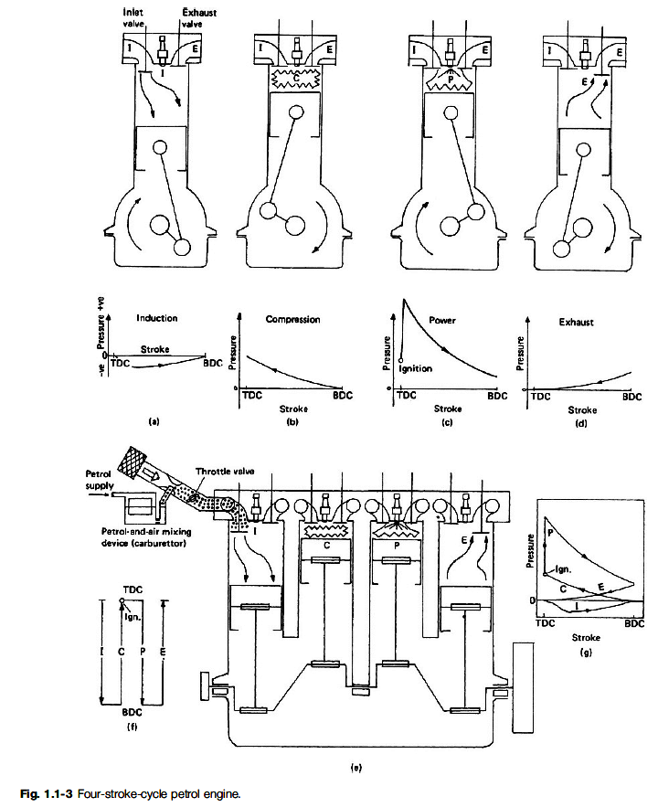
Intake Stroke
The engine cycle begins with the intake stroke as the piston is pulled towards the crankshaft (to the left in the figure).
The intake valve is open, and fuel and air are drawn past the valve and into the combustion chamber and cylinder from the intake manifold located on top of the combustion chamber. The exhaust valve is closed and the electrical contact switch is open. The fuel/air mixture is at a relatively low pressure (near atmospheric) and is colored blue in this figure. At the end of the intake stroke, the piston is located at the far left and begins to move back towards the right.
The cylinder and combustion chamber are full of the low pressure fuel/air mixture and, as the piston begins to move to the right, the intake valve closes.
Historical note - The opening and closing of the intake valve of the Wright 1903 engine was termed "automatic" by the brothers. It relies on the slightly lower pressure within in the cylinder during the intake stroke to overcome the strength of the spring holding the valve shut. Modern internal combustion engines do not work this way, but use cams and rocker arms like the brothers' exhaust system. Cams and rocker arms provide better control and timing of the opening and closing of the valves.
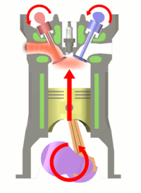
Compression Stroke
With both valves closed, the combination of the cylinder and combustion chamber form a completely closed vessel containing the fuel/air mixture. As the piston is pushed to the right, the volume is reduced and the fuel/air mixture is compressed during the compression stroke.
During the compression, no heat is transferred to the fuel/air mixture. As the volume is decreased because of the piston's motion, the pressure in the gas is increased, as described by the laws of thermodynamics. In the figure, the mixture has been colored yellow to denote a moderate increase in pressure. To produce the increased pressure, we have to do work on the mixture, just as you have to do work to inflate a bicycle tire using a pump. During the compression stroke, the electrical contact is kept opened. When the volume is the smallest, and the pressure the highest as shown in the figure, the contact is closed, and a current of electricity flows through the plug.
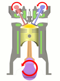
Power Stroke
At the beginning of the power stroke, the electrical contact is opened. The sudden opening of the contact produces a spark in the combustion chamber which ignites the fuel/air mixture. Rapid combustion of the fuel releases heat, and produces exhaust gases in the combustion chamber.
Because the intake and exhaust valves are closed, the combustion of the fuel takes place in a totally enclosed (and nearly constant volume) vessel. The combustion increases the temperature of the exhaust gases, any residual air in the combustion chamber, and the combustion chamber itself. From the ideal gas law, the increased temperature of the gases also produces an increased pressure in the combustion chamber. We have colored the gases red in the figure to denote the high pressure. The high pressure of the gases acting on the face of the piston cause the piston to move to the left which initiates the power stroke.
Unlike the compression stroke, the hot gas does work on the piston during the power stroke. The force on the piston is transmitted by the piston rod to the crankshaft, where the linear motion of the piston is converted to angular motion of the crankshaft. The work done on the piston is then used to turn the shaft, and the propellers, and to compress the gases in the neighboring cylinder's compression stroke. Having produced the igniting spark, the electrical contact remains opened.
During the power stroke, the volume occupied by the gases is increased because of the piston motion and no heat is transferred to the fuel/air mixture. As the volume is increased because of the piston's motion, the pressure and temperature of the gas are decreased. We have colored the exhaust "molecules" yellow to denote a moderate amount of pressure at the end of the power stroke.
Historical note - The method of producing the electrical spark used by the Wright brothers is called a "make and break" connection. There are moving parts located inside the combustion chamber. Modern internal combustion engines do not use this method, but instead use a spark plug to produce the ignition spark. A spark plug has no moving parts, which is much safer than the method used by the brothers.
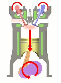
Exhaust Stroke
At the end of the power stroke, the piston is located at the far left. Heat that is left over from the power stroke is nowtransferred to the water in the water jacket until the pressure approaches atmospheric pressure. The exhaust valve is then opened by the cam pushing on the rocker arm to begin the exhaust stroke.
The purpose of the exhaust stroke is to clear the cylinder of the spent exhaust in preparation for another ignition cycle. As the exhaust stroke begins, the cylinder and combustion chamber are full of exhaust products at low pressure (colored blue on the figure above.) Because the exhaust valve is open, the exhaust gas is pushed past the valve and exits the engine. The intake valve is closed and the electrical contact is open during this movement of the piston.
At the end of the exhaust stroke, the exhaust valve is closed and the engine begins another intake stroke.
Historical note - The exhaust system used by the Wright brothers caused the hot exhaust to exit each cylinder independently ... right next to the pilot. This engine was very loud as well. Modern automobiles collect the exhaust from all of the cylinders into an exhaust manifold (just like the intake manifold used by the brothers). The exhaust manifold passes the exhaust to the catalytic converter to remove dangerous gases, and then through the muffler to keep it quiet, and finally out the exhaust pipe.
You should now be able to make some sense from the animation at the top of this page. Notice that the crankshaft makes two revolutions for every one revolution of the cams. This motion is controlled by the timing chain. Also notice how the cam moves the exhaust valve at just the right time and how quickly the intake valve opens after the exhaust valve is closed. In real engine operation, the exhaust stroke can not push all of the exhaust out of the cylinder, so a real engine doesn't perform as well as the ideal engine described on this page. As the engine runs and heats up, the performance changes. Modern automobile engines adjust the fuel/air ratio with computer controlled fuel injectors to maintain high performance. The brothers just had to watch the horsepower of their engine drop from about 16 horsepower when the engine was first started to about 12 horsepower when it was running hot.

A four-stroke engine (also known as four-cycle) is an internal combustion engine in which the piston completes four separate strokes which constitute a single thermodynamic cycle. A stroke refers to the full travel of the piston along the cylinder, in either direction. The four separate strokes are termed:
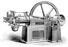
Nikolaus August Otto as a young man was a traveling salesman for a grocery concern. In his travels he encountered the internal combustion engine built in Paris by Belgian expatriate Jean Joseph Etienne Lenoir. In 1860, Lenoir successfully created a double-acting engine that ran on illuminating gas at 4% efficiency. The 18 litre Lenoir Engine produced only 2 horsepower. The Lenoir engine ran on illuminating gas made from coal, which had been developed in Paris by Philip Lebon.
In testing a replica of the Lenoir engine in 1861 Otto became aware of the effects of compression on the fuel charge. In 1862, Otto attempted to produce an engine to improve on the poor efficiency and reliability of the Lenoir engine. He tried to create an engine that would compress the fuel mixture prior to ignition, but failed as that engine would run no more than a few minutes prior to its destruction. Many other engineers were trying to solve the problem, with no success.
In 1864, Otto and Eugen Langen founded the first internal combustion engine production company, NA Otto and Cie (NA Otto and Company). Otto and Cie succeeded in creating a successful atmospheric engine that same year. The factory ran out of space and was moved to the town of Deutz, Germany in 1869 where the company was renamed to Deutz Gasmotorenfabrik AG (The Deutz Gas Engine Manufacturing Company). In 1872,Gottlieb Daimler was technical director and Wilhelm Maybach was the head of engine design. Daimler was a gunsmith who had worked on the Lenoir engine. By 1876, Otto and Langen succeeded in creating the first internal combustion engine that compressed the fuel mixture prior to combustion for far higher efficiency than any engine created to this time.
Daimler and Maybach left their employ at Otto and Cie and developed the first high-speed Otto engine in 1883. In 1885, they produced the first automobile to be equipped with an Otto engine. The Daimler Reitwagen used a hot-tube ignition system and the fuel known as Ligroin to become the world's first vehicle powered by an internal combustion engine. It used a four-stroke engine based on Otto's design. The following year Karl Benz produced a four-stroke engined automobile that is regarded as the first car.
In 1884, Otto's company, then known as Gasmotorenfabrik Deutz (GFD), developed electric ignition and the carburetor. In 1890, Daimler and Maybach formed a company known as Daimler Motoren Gesellschaft. Today, that company is Daimler-Benz.

The Atkinson cycle engine is a type of single stroke internal combustion engine invented by James Atkinson in 1882. The Atkinson cycle is designed to provide efficiency at the expense of power density, and is used in some modern hybrid electric applications.
The original Atkinson cycle piston engine allowed the intake, compression, power, and exhaust strokes of the four-stroke cycle to occur in a single turn of the crankshaft and was designed to avoid infringing certain patents covering Otto cycle engines.
Due to the unique crankshaft design of the Atkinson, its expansion ratio can differ from its compression ratio and, with a power stroke longer than its compression stroke, the engine can achieve greater thermal efficiency than a traditional piston engine. While Atkinson's original design is no more than a historical curiosity, many modern engines use unconventional valve timing to produce the effect of a shorter compression stroke/longer power stroke, thus realizing the fuel economy improvements the Atkinson cycle can provide.[4]
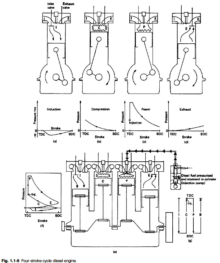
The diesel engine is a technical refinement of the 1876 Otto Cycle engine. Where Otto had realized in 1861 that the efficiency of the engine could be increased by first compressing the fuel mixture prior to its ignition, Rudolph Diesel wanted to develop a more efficient type of engine that could run on much heavier fuel. The Lenoir, Otto Atmospheric, and Otto Compression engines (both 1861 and 1876) were designed to run onIlluminating Gas (coal gas). With the same motivation as Otto, Diesel wanted to create an engine that would give small industrial concerns their own power source to enable them to compete against larger companies, and like Otto to get away from the requirement to be tied to a municipal fuel supply. Like Otto, it took more than a decade to produce the high compression engine that could self-ignite fuel sprayed into the cylinder. Diesel used an air spray combined with fuel in his first engine.
During initial development, one of the engines burst nearly killing him. He persisted and finally created an engine in 1893. The high compression engine, which ignites its fuel by the heat of compression is now called the Diesel engine whether a four-stroke or two-stroke design.
The four-stroke diesel engine has been used in the majority of heavy duty applications for many decades. It uses a heavy fuel containing more energy and requiring less refinement to produce. The most efficient Otto Cycle engines run near 30% efficiency.

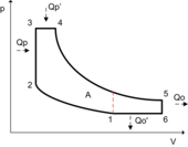
The thermodynamic analysis of the actual four-stroke or two-stroke cycles is not a simple task. However, the analysis can be simplified significantly if air standard assumptions are utilized. The resulting cycle, which closely resembles the actual operating conditions, is the Otto cycle.
During the normal operation of the engine as the fuel mixture is being compressed an electric arc is created to ignite the fuel. At low rpm this occurs close to TDC (Top Dead Centre). As engine rpm rises the spark point is moved earlier in the cycle so that the fuel charge can be ignited while it is still being compressed. We can see this advantage reflected in the various Otto engines designs. The atmospheric (non-compression) engine operated at 12% efficiency. The compressed charge engine had an operating efficiency of 30%.
The problem with compressed charge engines is that the temperature rise of the compressed charge can cause pre-ignition. If this occurs at the wrong time and is too energetic, it can damage the engine. Different fractions of petroleum have widely varying flash points (the temperatures at which the fuel may self-ignite). This must be taken into account in engine and fuel design.
The tendency for the compressed fuel mixture to ignite early is limited by the chemical composition of the fuel. There are several grades of fuel to accommodate differing performance levels of engines. The fuel is altered to change its self ignition temperature. There are several ways to do this. As engines are designed with higher compression ratios the result is that pre-ignition is much more likely to occur since the fuel mixture is compressed to a higher temperature prior to deliberate ignition. The higher temperature more effectively evaporates fuels such as gasoline, which increases the efficiency of the compression engine. Higher Compression ratios also mean that the distance that the piston can push to produce power is greater (which is called the Expansion ratio).
The octane rating of a given fuel is a measure of the fuel's resistance to self-ignition. A fuel with a higher numerical octane rating allows for a higher compression ratio, which extracts more energy from the fuel and more effectively converts that energy into useful work while at the same time preventing engine damage from pre-ignition. High Octane fuel is also more expensive.
Diesel engines by their nature do not have concerns with pre-ignition. They have a concern with whether or not combustion can be started. The description of how likely Diesel fuel is to ignite is called the Cetane rating. Because Diesel fuels are of low volatility, they can be very hard to start when cold. Various techniques are used to start a cold Diesel engine, the most common being the use of a glow plug.
The maximum amount of power generated by an engine is determined by the maximum amount of air ingested. The amount of power generated by a piston engine is related to its size (cylinder volume), whether it is a two-stroke or four-stroke design, volumetric efficiency, losses, air-to-fuel ratio, the calorific value of the fuel, oxygen content of the air and speed (RPM). The speed is ultimately limited by material strength and lubrication. Valves, pistons and connecting rods suffer severe acceleration forces. At high engine speed, physical breakage and piston ring flutter can occur, resulting in power loss or even engine destruction. Piston ring flutter occurs when the rings oscillate vertically within the piston grooves they reside in. Ring flutter compromises the seal between the ring and the cylinder wall, which causes a loss of cylinder pressure and power. If an engine spins too quickly, valve springs cannot act quickly enough to close the valves. This is commonly referred to as 'valve float', and it can result in piston to valve contact, severely damaging the engine. At high speeds the lubrication of piston cylinder wall interface tends to break down. This limits the piston speed for industrial engines to about 10 m/s.
The output power of an engine is dependent on the ability of intake (air–fuel mixture) and exhaust matter to move quickly through valve ports, typically located in the cylinder head. To increase an engine's output power, irregularities in the intake and exhaust paths, such as casting flaws, can be removed, and, with the aid of an air flow bench, the radii of valve port turns and valve seat configuration can be modified to reduce resistance. This process is called porting, and it can be done by hand or with a CNC machine
One way to increase engine power is to force more air into the cylinder so that more power can be produced from each power stroke. This can be done using some type of air compression device known as a supercharger, which can be powered by the engine crankshaft.
Supercharging increases the power output limits of an internal combustion engine relative to its displacement. Most commonly, the supercharger is always running, but there have been designs that allow it to be cut out or run at varying speeds (relative to engine speed). Mechanically driven supercharging has the disadvantage that some of the output power is used to drive the supercharger, while power is wasted in the high pressure exhaust, as the air has been compressed twice and then gains more potential volume in the combustion but it is only expanded in one stage.
A turbocharger is a supercharger that is driven by the engine's exhaust gases, by means of a turbine. It consists of a two piece, high-speed turbine assembly with one side that compresses the intake air, and the other side that is powered by the exhaust gas outflow.
When idling, and at low-to-moderate speeds, the turbine produces little power from the small exhaust volume, the turbocharger has little effect and the engine operates nearly in a naturally aspirated manner. When much more power output is required, the engine speed and throttle opening are increased until the exhaust gases are sufficient to 'spin up' the turbocharger's turbine to start compressing much more air than normal into the intake manifold.
Turbocharging allows for more efficient engine operation because it is driven by exhaust pressure that would otherwise be (mostly) wasted, but there is a design limitation known as turbo lag. The increased engine power is not immediately available due to the need to sharply increase engine RPM, to build up pressure and to spin up the turbo, before the turbo starts to do any useful air compression. The increased intake volume causes increased exhaust and spins the turbo faster, and so forth until steady high power operation is reached. Another difficulty is that the higher exhaust pressure causes the exhaust gas to transfer more of its heat to the mechanical parts of the engine.
The rod-to-stroke ratio is the ratio of the length of the connecting rod to the length of the piston stroke. A longer rod reduces sidewise pressure of the piston on the cylinder wall and the stress forces, increasing engine life. It also increases the cost and engine height and weight.
A "square engine" is an engine with a bore diameter equal to its stroke length. An engine where the bore diameter is larger than its stroke length is an oversquare engine, conversely, an engine with a bore diameter that is smaller than its stroke length is an undersquare engine.
The valves are typically operated by a camshaft rotating at half the speed of the crankshaft. It has a series of cams along its length, each designed to open a valve during the appropriate part of an intake or exhaust stroke. A tappet between valve and cam is a contact surface on which the cam slides to open the valve. Many engines use one or more camshafts “above” a row (or each row) of cylinders, as in the illustration, in which each cam directly actuates a valve through a flat tappet. In other engine designs the camshaft is in the crankcase, in which case each cam contacts a push rod, which contacts a rocker arm that opens a valve. The overhead cam design typically allows higher engine speeds because it provides the most direct path between cam and valve.
Valve clearance refers to the small gap between a valve lifter and a valve stem that ensures that the valve completely closes. On engines with mechanical valve adjustment, excessive clearance causes noise from the valve train. A too small valve clearance can result in the valves not closing properly, this results in a loss of performance and possibly overheating of exhaust valves. Typically, the clearance must be readjusted each 20,000 miles (32,000 km) with a feeler gauge.
Most modern production engines use hydraulic lifters to automatically compensate for valve train component wear. Dirty engine oil may cause lifter failure.
Otto engines are about 30% efficient; in other words, 30% of the energy generated by combustion is converted into useful rotational energy at the output shaft of the engine, while the remainder being losses due to waste heat, friction and engine accessories. There are a number of ways to recover some of the energy lost to waste heat. The use of a Turbocharger in Diesel engines is very effective by boosting incoming air pressure and in effect provides the same increase in performance as having more displacement. The Mack Truck company, decades ago, developed a turbine system that converted waste heat into kinetic energy that it fed back into the engine's transmission. In 2005, BMW announced the development of the turbosteamer, a two-stage heat-recovery system similar to the Mack system that recovers 80% of the energy in the exhaust gas and raises the efficiency of an Otto engine by 15%. By contrast, a six-stroke engine may reduce fuel consumption by as much as 40%.
Modern engines are often intentionally built to be slightly less efficient than they could otherwise be. This is necessary for emission controls such as exhaust gas recirculation andcatalytic converters that reduce smog and other atmospheric pollutants. Reductions in efficiency may be counteracted with an engine control unit using lean burn techniques.
In the United States, the Corporate Average Fuel Economy mandates that vehicles must achieve an average of 34.9 miles per gallon (mpg) compared to the current standard of 25 mpg. As automakers look to meet these standards by 2016, new ways of engineering the traditional internal combustion engine (ICE) could have to be considered. Some potential solutions to increase fuel efficiency to meet new mandates include firing after the piston is farthest from the crankshaft, known as top dead centre, and applying theMiller cycle. Together, this redesign could significantly reduce fuel consumption and NOx emissions.


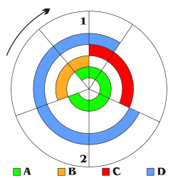
Starting
position, intake stroke, and compression stroke.
Ignition of fuel, power
stroke, and exhaust stroke.